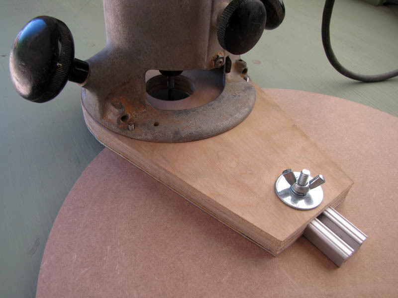
This attachment mounts in place of your router’s factory baseplate and is used for cutting circular disks from, or boring circular holes in, sheet stock. It pivots about a small pin rotating in a blind hole drilled in the center of the stock to be cut. This one is based on a design from Bill Hylton’s excellent book Router Magic.

As much as I like Hylton’s project, I wanted to design a DIY trammel that did not require any table-mounted tools or expensive router bits for its construction. My version is laminated from three layers of quarter-inch stock, and replaces Hylton’s custom-milled T-slot and matching arm with a short piece of aluminum 80/20 rail, which is inexpensively available. The arm can be reversed in the slot to cut small radii, and Hylton’s dimensions have been slightly modified to provide a continuous range of possible diameters of about 2-22″.

Project Steps

Cut arm to length

Hylton’s design calls for an 8-inch arm, which is the length I started with. But I eventually decided to cut mine down to 6 inches so that there would be no radius between 1.5 and 22 inches that I could not cut. With a 1/4″ bit, a longer arm will have a gap in the range of possible radii between the pin-out and pin-in arm positions.

Use a metal rule to measure six inches from one end of the stock 80/20 rail. Mark the location.

Use a hacksaw with a fine-tooth blade to cut the rail to length.

My cheap plastic miter box was a convenient clamping means, but not dependable for keeping the cut square and true. Fortunately, a perfectly square cut is not necessary for this design. If I were to do it again, I’d just freehand this cut.

Mark and drill pivot pin hole

The 80/20 channel has a center line extruded into its inside surface.

Position a metal rule as shown and use a hobby knife or other sharp steel tool to nick the centerline one-half inch in from the factory-cut end of the arm.

Drill a 1/8-inch diameter hole through the rail at the nick. Use a sharp twist drill, a drop of cutting fluid, and a slower drill speed.

Mark baseplate edge and center

The router should be turned off and unplugged until the last step of this project.

Chuck the countersink into the router collet.

Position the router in the corner of the 1/4″ stock, with the edges of the stock just tangent to the router base on both sides of one corner, as shown.

Trace around the base of the router with a sharp pencil.

To accurately mark the bit location, manually depress the router’s height adjustment (or plunge adjustment, if it has one) pushing the tip of the countersink into the plywood. Be sure not to move the base as you do so.

Carry center and diameter to stock edges

Use a framing square, as shown, to carry the center point to the edges of the stock. The distance to the corner should be the same on each side. In my case, this distance was 3 inches.

Use the square, again, as shown, to carry the diameter of the router base to the edges of the stock. The distance to each corner should be exactly twice that of the smaller square; in my case, 6 inches.

Mark base edge- and center-lines

Using a steel rule, measure 6.5 inches from the router’s center point, along one edge of the stock, and make a witness mark.

Use the framing square to extend a rectangle that includes the baseplate diameter and the witness mark.

Measure and mark the center of the distant edge, then connect it to the center of the near edge with a line.

Mark bolt and channel locations

To locate the bolt hole, measure 0.75″ in from the distant edge, along the base centerline, and make a witness mark first with a pencil, then with a center punch.

Lay the cut 80/20 rail on the stock, open side up, as shown, aligning the rail’s centerline with the base centerline at each end.

Trace the long edges of the rail onto the base with a pencil.

Measure out 1 inch from each side of the channel, along the distant edge of the base, connect those points with tangent lines to the baseplate perimeter. I forgot this step until later in the project, but it makes more sense to do it now.

Rough cut base layers

Use a 24-tpi blade in a saber saw to cut out the base along the outermost rectangle. Cut to preserve the outline.

Trace two copies of the cut-out rectangle onto the plywood sheet, and cut them out as well, again cutting to preserve the outlines.

If I were to do it again, I would lay out the rectangles with their short edges along the factory-straight edge of the stock, to save time in truing them up later.

Tape base layers together

Cover one side of each of the unmarked plywood rectangles with strips of carpet tape.

Peel the backing off the carpet tape, align the rough edges of the layers as closely as you can, and press them together.

Make sure the marked blank is on top, with the marks visible.

I used carpet tape to join all three base layers, but it turns out only one of the two joints needs to be demounted later. If I were to do it again, I’d just go ahead and glue the marked layer to one of the others at this point, and then carpet tape those two layers to the third. See step 13 for gluing details.

Temporarily affix factory baseplate

Remove your router’s factory baseplate, and cover the bottom with strips of carpet tape.

Before peeling off the tape backing, turn the baseplate over on a cutting board and trim the extra tape by tracing around the edge with a hobby knife.

Take a minute to think about how you want the router mounted relative to the trammel arm when the tool is in use. Do you want the cord running to the inside or the outside of the circle, for instance?

Once you’ve figured it out, peel off the tape backing, align the baseplate with its traced outline, and press it down.

Drill mounting holes

Select a drill bit that matches the diameter of the mounting holes in the factory baseplate.

Chuck the bit into your drill and, using the factory baseplate as a template, drill corresponding mounting holes through all three layers of the base.

Using your holesaw’s pilot bit, or a bit of the same diameter, drill a hole in the center of the router footprint, right where the router bit would be.

Switch to a 5/16″ bit and drill the bolt-hole through all three layers of the base.

Cut bit opening

Select a holesaw that closely matches the inner diameter of the router’s factory baseplate.

Remove the factory baseplate from the stack and clean off the carpet tape.

Using the pre-drilled hole at the baseplate center to guide the holesaw’s pilot bit, cut a hole through all three layers of the stack. To prevent tearouts, cut halfway through from one side, then turn the stack over and finish the hole from the other.

Cut arm channel

Remove one layer from the stack, from the side opposite the marked layer. You will cut the marked layer, and one more attached to it. Remove the remaining bits of carpet tape.

Use the leftover 80/20 rail as a straightedge to guide the saber saw. Put a strip of carpet tape on the bottom to help hold it in place.

Butt the saw baseplate against the rail, position the blade to cut just inside the marked channel edge, and make sure the rail is aligned parallel to the line.

Make the first cut.

Instead of moving the taped section of 80/20 rail to make the second cut, like I did, just slide the cut-off section of 80/20 rail against it and use it as a spacer. This should position the second cut at exactly the right distance from the first.

Countersink mounting holes

Countersink the three mounting holes in the marked layer (which will be the bottom of the finished base) so that the mounting screws will tighten down flush.

Glue layers together

Remove the countersink or other bit from your router. Remove the holesaw from its pilot bit.

Verify that the layers will be stacked in the same arrangement in which they were drilled, then apply glue to one of the two surfaces in each joint. Align them as well as you can, visually, and stack them back up.

While the glue is still wet, position the stack on your router and loosely install the mounting screws. Slide the arm into the channel and the loose holesaw into the bit opening to help make sure everything is aligned correctly, then tighten the mounting screws down all the way.

Remove the arm and the holesaw, turn everything over, and position the stack, with the router still attached, on a flat surface to dry overnight.

Make sure to clamp or weight the end opposite the router while the glue is drying. I used a scrap of plate glass and some spring clamps, as shown, but a flat garage floor with some weights should work just as well.

Cut outer profile

When the glue is dry, the trammel is functionally ready to use. I wanted to nicely shape the outer edge for the sake of appearance, but if you don’t care how it looks you can skip this step altogether.

Clamp the base securely to the end of a sawhorse as shown. You may want to use spacers to keep the clamp jaws from marring it.

Use the saber saw to rough-cut the outer profile of the base to the layout lines on its underside.

Be careful trying to cut tight radii with a saber saw blade, as it will tend to “bank” outwards at the bottom of the cut. Instead, make a series of straight cuts tangent to the edge and file the curve smooth afterward.

Use a rasp and/or file to smooth the rough-cut edges to shape.

Install pivot pin

Tap the tension pin into the hole in the arm. Start the pin with a lightweight hammer, then switch to a heavier one, if necessary, as it drives in.

Drive the pin into the hole until the head of the carriage bolt just clears it sliding past. About 1/4″ should be protruding below the arm.

Assemble

Though I think the aluminum “shoe” on the bottom of my trammel looks kinda cool, it is the result of an error on my part, and if you learn from my mistake, you won’t have to install one on yours. See the conclusion for an explanation.

The arm can be slid into the channel from either end. Use it in the pin-out orientation for large radius cuts, and reverse it for small radii.

Slide the head of the carriage bolt into the arm. The square underside carriage bolt head should just fit into the neck of the rail profile.

Align the protruding bolt threads with the bolt-hole, and the arm with the cut channel, and guide the arm into the channel and the bolt through the hole in one motion.

Slip the fender washer over the bolt, and then the split washer. Then add the wingnut and tighten it down.

Secure stock for cutting

To cut a circle, first select a sacrificial substrate. I used a piece of leftover chipboard from another project.

Apply an “X” of carpet tape to one corner of the substrate, where the circle will be cut. This will prevent the cut-out circle from sliding around as the cut is completed and possibly marring its edge.

Peel the backing from the tape and lay the stock to be cut down on top of the substrate.

Clamp the stock and substrate, together, to your sawhorses, bench, or other secure work surface.

Mark and drill center

This step and the next describe the procedure used for cutting a circle tangent to the edge of a piece of stock, which is an easy way to do it if you don’t have a plunge router. If you do, the process is a lot simpler: Locate the center of the circle, drill the hole, set up the trammel, turn it on, plunge the bit, and make the cut.

In one corner of your stock, use the framing square to mark the corner of a square with sides equal to the radius of the circle you want to cut. Also make a short witness mark at one of the edges of the stock.

Chuck a 1/8″ bit into your drill with only 1/4″ of its length protruding. If you can’t do this, install a bit stop 1/4″ from the end, or mark it with a piece of tape.

Drill a 1/8″ diameter hole 1/4″ deep at the corner of the square.

Adjust trammel arm

Attach the trammel to the router with the flathead mounting screws.

With the pivot pin in the blind center hole in the stock, set the length of the trammel arm so that the router bit abuts the stock edge just at the witness mark.

Set the router’s height adjustment so that the bit extends about 1/16″ below the thickness of the stock to be cut.

Make the cut

You should be familiar with the safe procedure for operating your router already, but at a minimum, it requires that you wear adequate gloves, safety glasses, and hearing protection.

Before you plug anything in, think about what the router power cord is going to be doing as you make the cut. I built my trammel such that the router’s cord is directed toward the center of the circle, so that I could hang the cord from an overhead hook and the router would pivot around it as the cut is made.

I believe the correct feed direction for this setup is actually clockwise, as viewed from the top, i.e. opposite the direction shown in the photo.

Make sure everything is positioned correctly, and that the trammel arm wingnut and the stock clamps are tight.

Plug the router in, grasp it securely, turn it on, and begin to feed the cut. Back the bit out, a bit, as necessary to clear the chips.

Feed slowly at the beginning and end of the cut and near the edge of the stock.

When the cut is complete, turn off and unplug the router and set it aside. Peel up the cut circle and remove the tape.

Conclusion

Although the aluminum "shoe" on my trammel looks pretty cool, it's the result of an error. I committed the third classic blunder and assumed that the nominal 1/4" plywood I bought at the hardware store was actually 1/4" thick. It was actually quite a bit thinner, and I had to make up the difference at the bottom with aluminum sheet so that the 80/20 rail, which is precisely 0.50" thick, wouldn't stick out.

Turns out true 1/4" plywood is very hard to find. Fortunately, true 1/4" MDF is available from most hardware stores. Take a gauge or micrometer with you to the store and check to make sure, before you buy. If you don't have a micrometer, take the 80/20 extrusion, itself, and verify that two of whatever you want to buy, stacked together, are just as thick.