[youtube:http://youtu.be/EXlDcKeUq14]

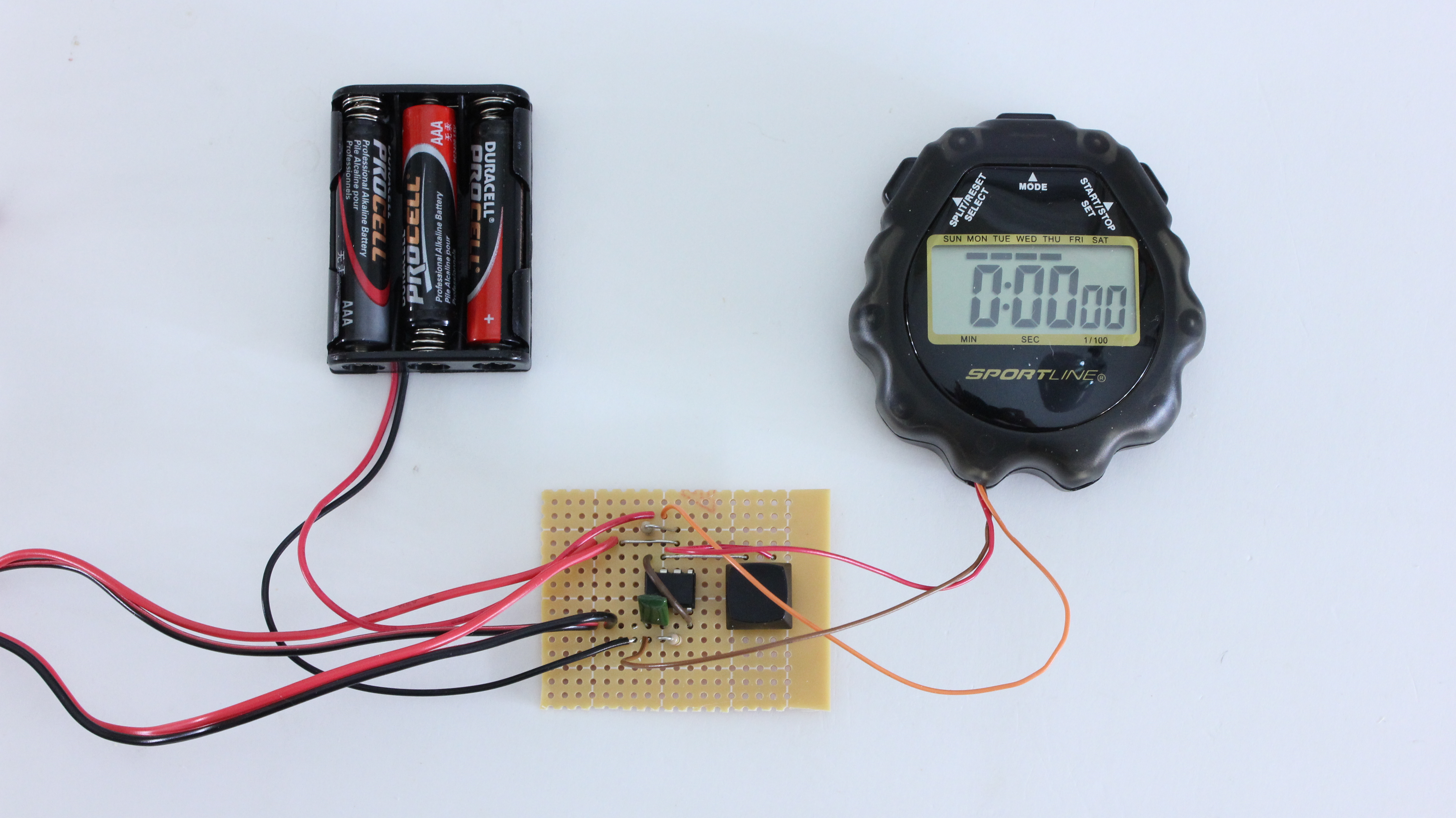
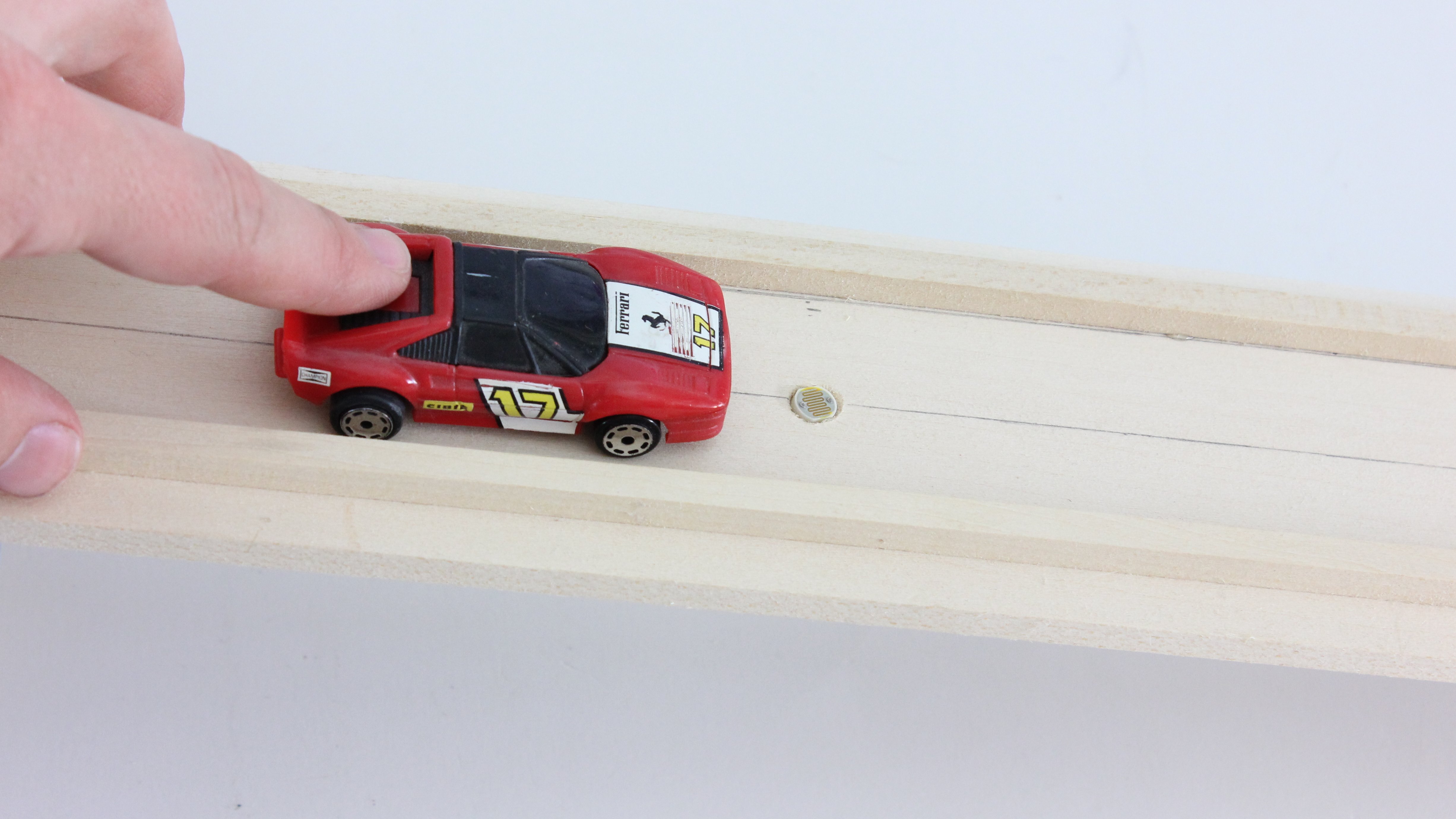
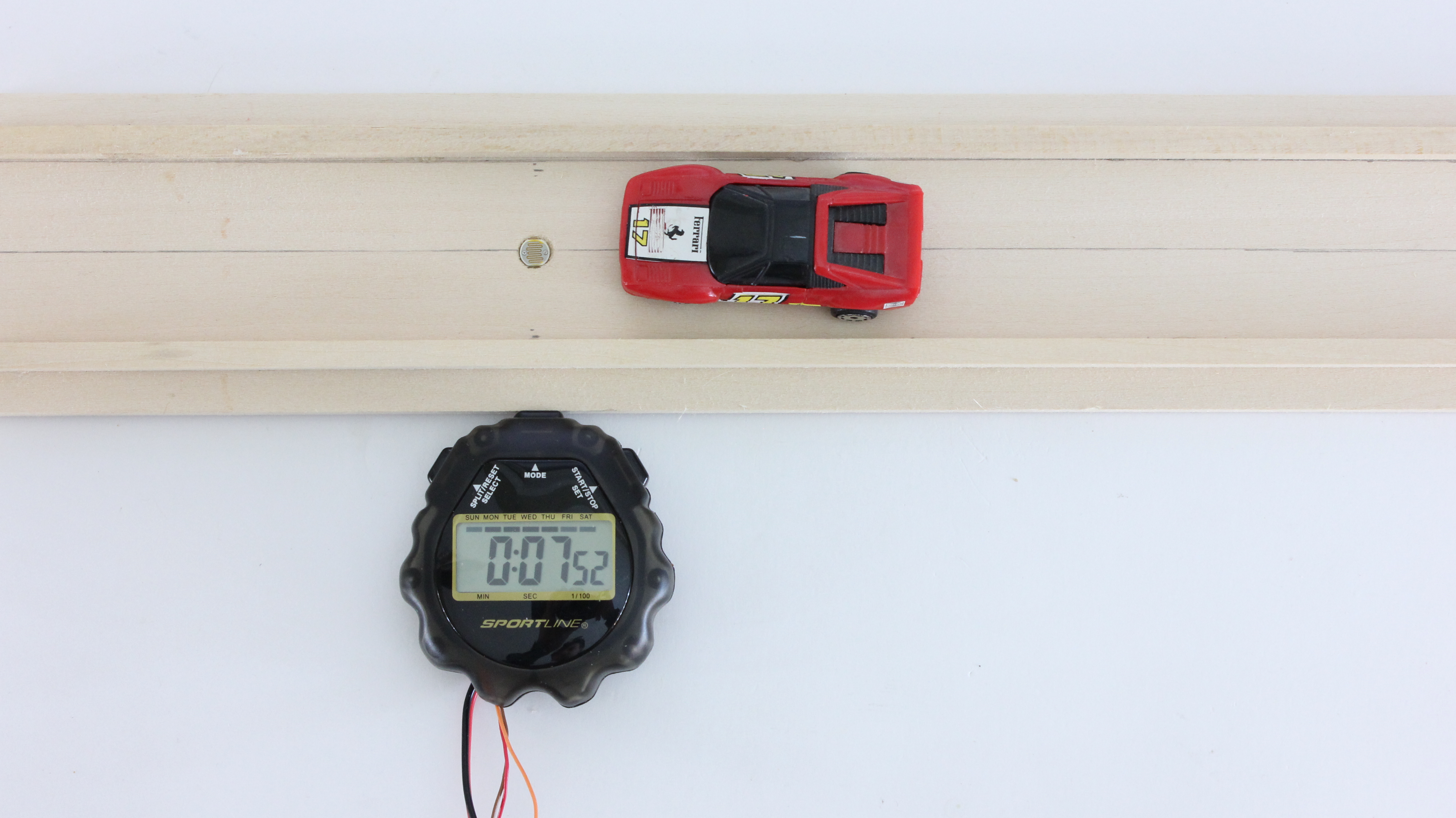
Racing toy cars, like Pinewood Derby or CO2 dragsters, is a lot of fun. But if you want to compare the results of multiple races, you need be able to accurately record the finishing times of each one. To do this, I designed a timer circuit that will automatically record the finishing times.

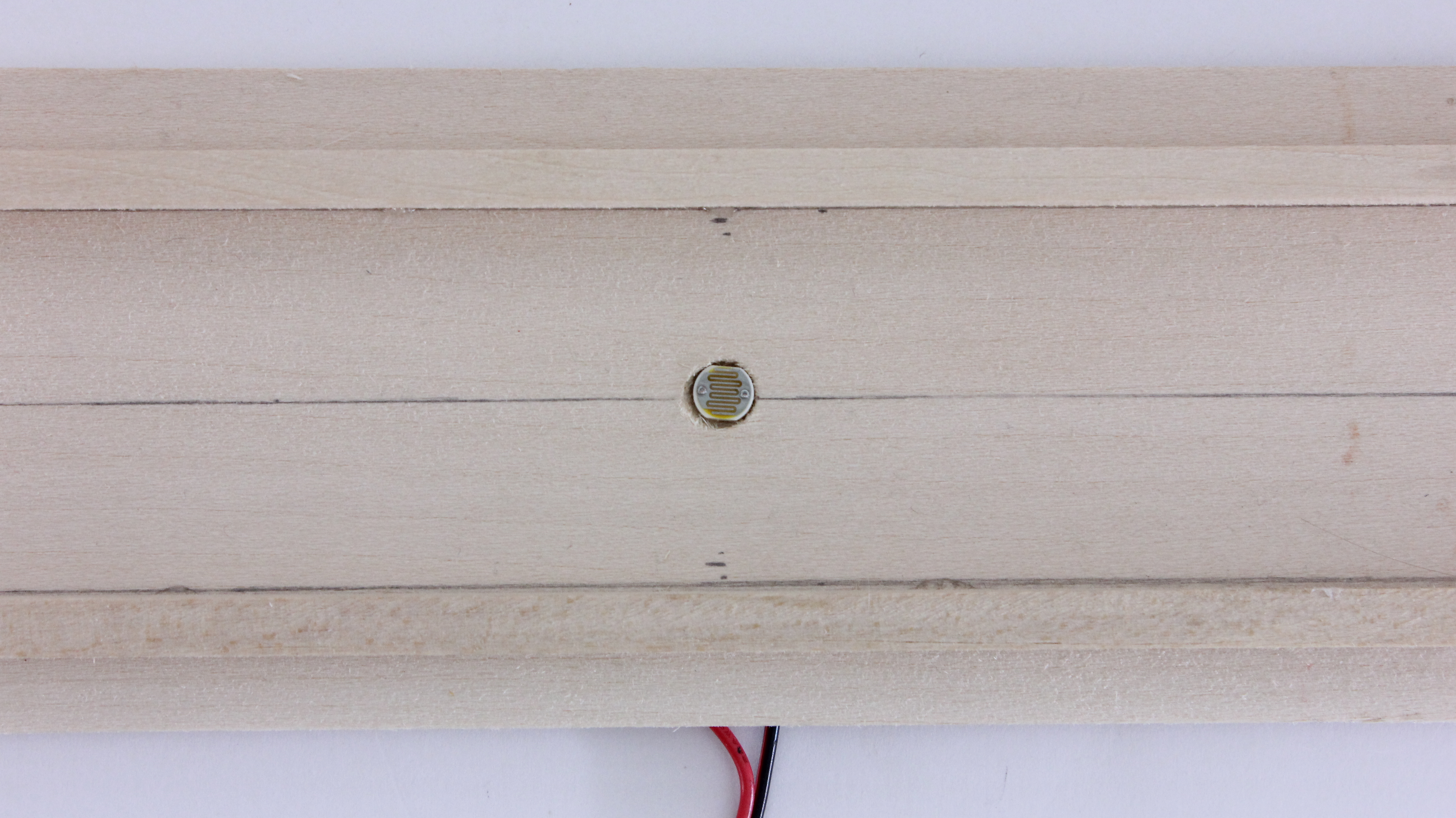
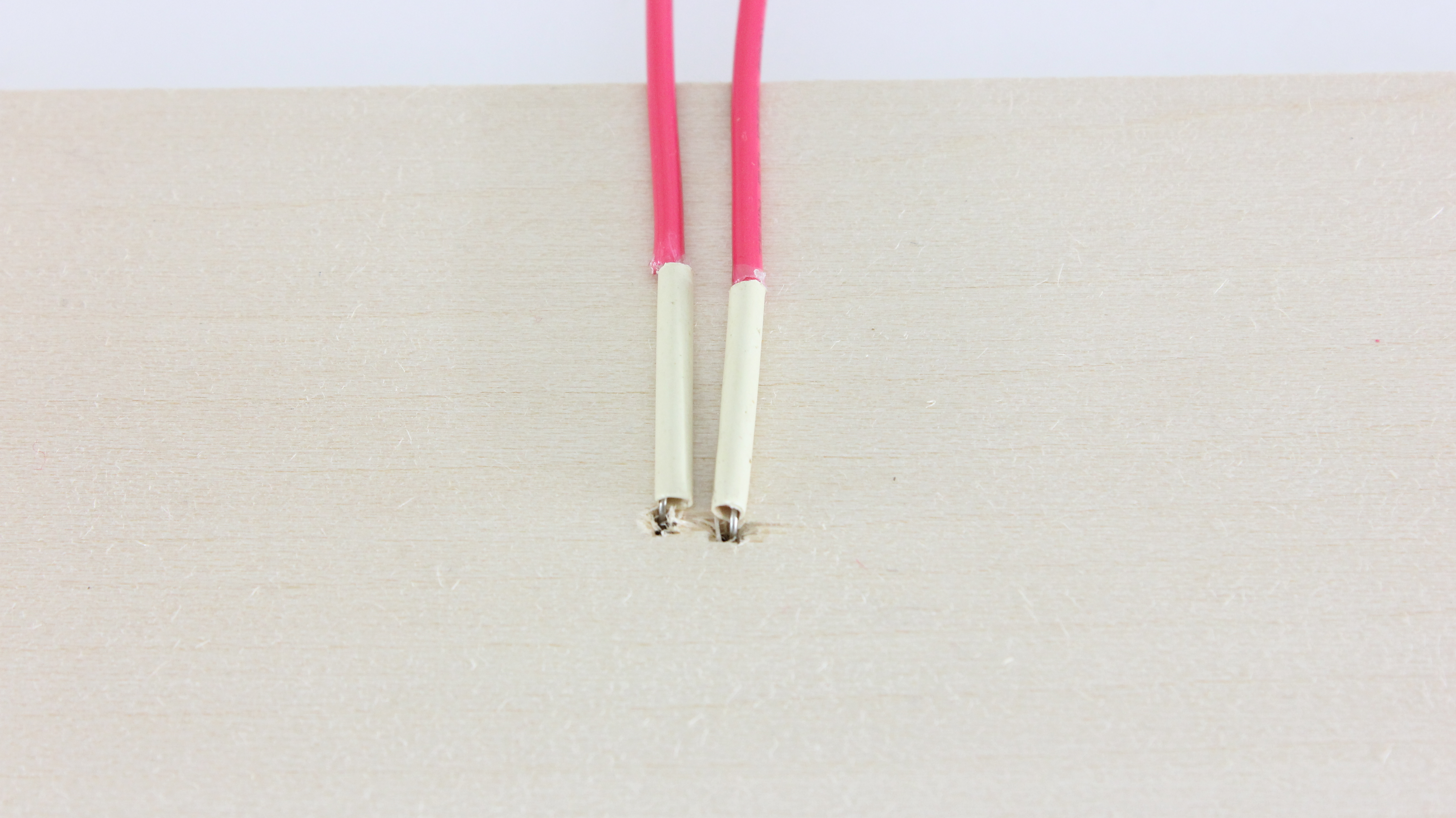
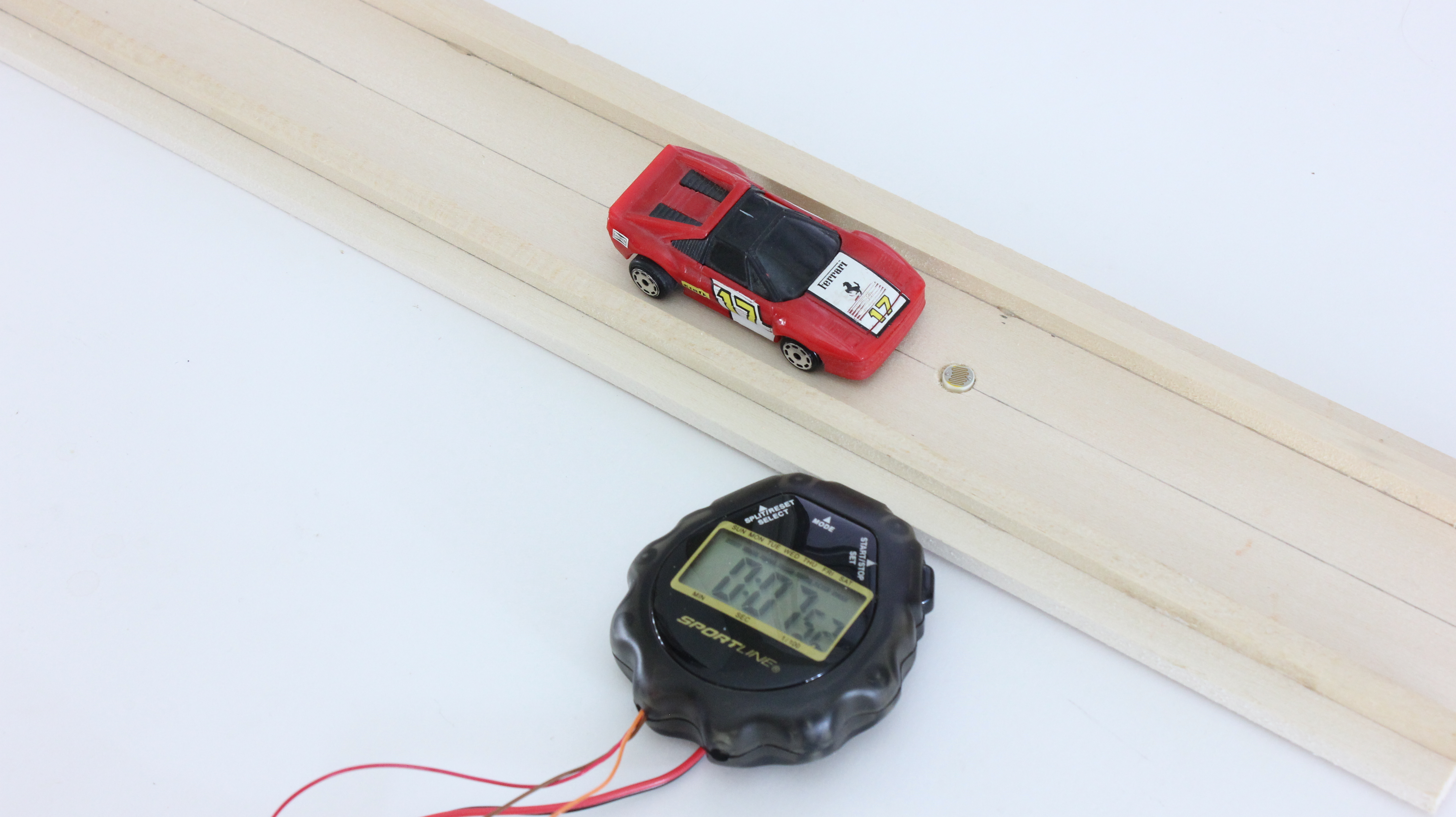
Two light sensors are mounted on a track. The first one is positioned just in front of the starting line. The second is located at the finish line. When the car crosses the first sensor, it starts the timer. Then when the car crosses the second sensor, it stops the timer. This lets you automatically record the finishing time of each car.

The system that I built is tailored to toy car races but it can easily be adapted for other kinds of races.

Project Steps

Open the Stopwatch and Locate the Button Contacts on the Circuit Board

​The first thing that you need to do is open up the housing of the stopwatch so that you can access the internal circuit. In most cases, the housing will be held together with a few screws. However, if your stop watch is held together with glue, then you may need to cut the plastic.

Inside, you will see the circuit board. You need to be able to solder wires onto the button contacts and the battery holder. If you cannot easily access these then you need to remove the circuit board from the housing. This will probably involve removing a few more screws.

Solder an Extension Wire Onto the Button Contacts and the Battery Holder

​In order to be able to control the stop watch remotely, we need to solder extension wires onto the contacts for the “Start/Stop” button and the “Reset” button.

You also need to solder one wire onto the battery holder. (Never solder onto a battery itself! Always remove the battery before soldering onto the battery holder!) You want to solder it onto the terminal that is connected to the other side of the switches. In my case, that was the positive terminal.

Cut a Slot in the Housing of the Stop Watch for the Extension Wires

​You need to route the wires outside the housing of the stop watch. If there are no openings where you can route the wires, then you need to make one. Take a sharp knife and carefully cut a slot in the housing that is just big enough for the wires.

When you are done, fit the wires into the cut slot and reassemble the housing.

The Control Circuit

​This is the control circuit that I designed for this project. It is built around a 555 timer IC. Power for the circuit is provided by three AAA batteries. The pin 7 output is connected to the “Start/Stop” button on the stop watch. The GND output is connected to the positive terminal of the battery holder on the stop watch.

The two light sensors are wired in parallel. These are wired in series with a fixed resistor. Together they make a ​voltage divider. When either of the light sensors is put in shadow (by the car driving over it), its resistance increases. This causes the voltage at pin 6 to go above the reference threshold. When this happens the output at pin 7 is connected to ground and activates the timer.

The two light sensors (photoresistors) need to be chosen so that each one has approximately the same resistance. The value of the series resistor (R1) should be about the same as the value of the two light sensors in parallel. You can replace the fixed resistor with a variable resistor (potentiometer) if you want to make the sensitivity adjustable. R2 can be any value higher than 10Kohm. I used 100Kohm. The capacitor can be any value higher than 0.001 microfarad. I used 0.01 microfarard.

The reset button on the stop watch is connected to a switch. The other side of the switch is connected to the positive terminal of the battery pack. This is not shown in the diagram.

Prototype the Control Circuit on a Breadboard

​It is always a good idea to prototype a circuit on a breadboard before soldering it together. This is especially true when working with photoresistors because they don’t have standard values. You may need to change the value of the series resistor to compensate for different lighting.

Once everything is connected, cover up one sensor. The timer should start. Then cover up the other sensor. The timer should stop. Lastly press the button and the timer should reset.

Solder the Circuit Together on a Circuit Board

​Once the circuit is working to your satisfaction, solder the parts onto a printed circuit board or perf board. The light sensors will not be soldered directly to the board. Instead, they will be connected by a pair of long extension wires. This will allow then to be mounted to the track.

Mount the Light Sensors on the Track

​The last step is to mount the light sensors onto the track. Find a drill bit that is slightly larger than the light sensor. Drill into the top side of the track just enough that you will be able to fit the head of the light sensor inside it. Then drill two smaller holes inside it for the leads of the light sensor. Fit the light sensor into the hole. Connect the wires from the circuit board onto the leads of the light sensor on the bottom side of the track. Do this at both the starting line and the finish line.

Finished Race Timer

​Now your automatic race timer is complete. When a car rolls over the sensor at the starting line, it will start the timer. When the car rolls over the sensor at the finish line it will stop the timer. You can use this time with a single lane track or you can make multiple timers for a mutli-lane track. However you use it, it will add a lot of fun to your toy car races.