


Have you ever thought you might like to:
- Grow, raise, and preserve your own food?
- Make observations and do amateur investigations in earth sciences and biology?
- Make structures using natural building techniques like cob or straw bale?
- Build systems for harvesting and caching the water and energy that already flow through the place you live?
If the idea of combining these and related activities to create a sustainable way of life sounds appealing, you may be interested in the practice known as “permaculture.”
What is Permaculture
The modern practice of permaculture was founded by Bill Mollison and David Holmgren in the 1970s as the practice of designing and building sustainable human settlements. The permanence of permaculture lies in its sustainability; it’s a design system that’s based on close observation of nature to create a way of life that has the same resiliency as a balanced ecosystem.
Permaculturists, or “permies” for short, are infused with optimism, a fascination with the workings of living systems and the land, and a delight in experimentation and making things.
Permaculture is a generalist’s delight, a practice that encourages dabbling in many of the arts and sciences, and a culture that embraces DIY activities of all kinds: lush gardens, biodynamic farming, herbal medicine, wildcrafting, tracking, and using earthmoving equipment to build ponds and swales, to name a few.
The first step in creating a permaculture design for a piece of property is to get to know the land in detail, ideally at different times of day (and night), through all four seasons, and in a variety of conditions. Creating a hand-drawn map of your property is one way to get to know your land, and your map will be a useful tool for developing a plan of action.
SKETCH YOUR LOT
TOOLS AND MATERIALS
- Large sheet of paper in a sketchbook or on a clipboard, to carry around your yard sketching out the property and recording measurements
- Pencils
- Tape measure the longer the better. You can get a good 300′ reel tape measure for about $30. Most of these are marked with feet and inches on one side, and feet and tenths of a foot on the other side.
- Marking flags and string (optional) helpful if some of your measurements will be longer than your tape measure
- Architect’s scale Available in most art supply stores with the drafting supplies, they look like 3-sided rulers. Architect’s scales are usually better than engineer’s scales for home-scale mapping.
- Straightedge or ruler for drawing lines
- Large, good quality paper for your final map
- Drawing compass If you’re buying one, get one with an extender for drawing large arcs.
- Tracing paper or vellum
- Masking or drafting tape (optional) if you want to do overlays on your finished map
- Pens, colored pencils, markers, and/or watercolor pencils or paints for coloring and finishing your map
To get started, take a walk around your property and notice the shapes of large features such as buildings and fences.
Look for a couple of good anchor points — permanent structures with well-defined edges. You should be able to pull the tape measure straight between these 2 anchor points, and to several other points in your yard.
Draw a quick sketch of the property, noting the features you want to include on your map. Just rough in the shape of your house and other buildings, and don’t worry about trying to make it to scale.
Draw your sketch as large as your paper allows, because you’ll be adding lots of lines and measurements that will crowd the page.
Measure the distance between your anchor points and write it down on the map. Keep the tape measure anchored at the first point, and measure to as many other points or corners as you can reach, recording them on your sketch. Then move to the second anchor point, and do the same.
Be sure to measure to each point twice — once from the first anchor point, and once from the second anchor point — because you’ll be using triangulation when you draw your map.
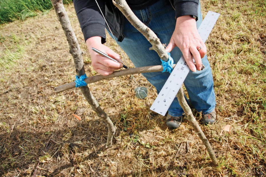
I also like to measure along any edges that are square, like the sides of a house or building (Figure A), because you don’t need to triangulate to each corner of your house if it’s really a right-angled box.
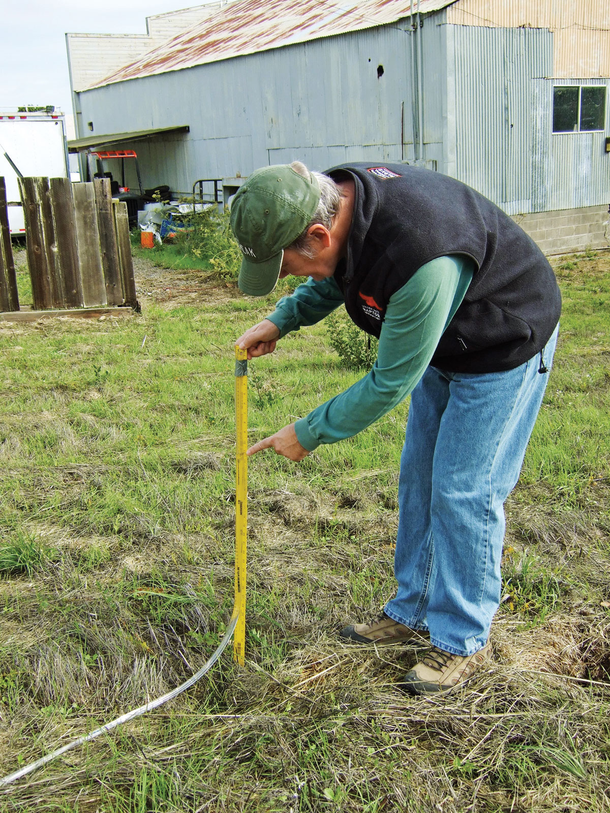
NOTE: Make sure to pull the tape measure taut over long distances — if it sags into a big curve, the distance you record could be more than a foot longer than it really is.


You’ll probably find that you can’t reach every point on your property from these 2 anchor points. That’s OK; just pick 2 other points you’ve measured, and use them as new anchor points. You can have as many new anchor points as you need.
If you need to measure a distance that’s longer than your tape (and you can’t use new anchor points to work around it), tie a string taut between the points to mark a straight line. Measure as far as you can along the string, and plant a stake flag in the ground, then measure the next section along the string. Repeat until you can add up your segments to get the full distance.
Your sketch will have several measuring lines radiating out from each of the anchor points, and their measurements. It may get quite messy, but don’t worry too much about that. If you need to record too many measurements in a tight space, you can always make a larger sketch for that detail area (Figure B).
MEET THE ARCHITECT’S SCALE
When you have all your measurements written down, it’s time to start working on your actual map. First, get familiar with your architect’s scale.
Each edge of the architect’s scale is marked for a different scale of measurement. For example, on the 3/32 scale, each tick mark of 3/32" represents 1 foot on the map. In this way, the scale saves you from doing the math to convert all your measurements.
If your measurement is 11′, you’ll use the distance between 0 and 11 along the edge of the scale (Figure C). Note that the scale doesn’t start at zero; the marks to the left of the zero are for fractions.
So if you want to mark off 12-1/2 feet, you can start from the 1/2-foot mark to the left of the zero, and then measure up to the 12th tick mark. This way the scale doesn’t have a jumble of thousands of tiny subdividing tick marks.

You want your map to be as large as possible, yet still fit on the paper. Look at your longer measurements and estimate the length of the longest edge of your property; then look at your architect’s scale and decide which scale to use so that the longest edge will fit. It’s a good practice to have the top of your map oriented at least roughly toward north.
DRAW YOUR MAP
Place a dot on the paper to represent your first anchor point. Then use the architect’s scale to measure the distance to the second anchor point, and place a dot on the paper for that.
Choose the next point to add to the map (it’s best to go in the same order in which you measured, in case any of these points become anchors later). Using the architect’s scale, set your compass to the distance from the first anchor point to this point.
Center the compass on the dot for the first anchor point and strike an arc about where you estimate the new point will land. Then set the compass for the distance from the second anchor point to the new point; center it on the second anchor point and strike another arc — the arcs intersect at the location of the new point (Figure D).

Continue to draw your map, using the compass and measurements to triangulate each point. You might find that your compass won’t extend to the longer measurements, even with an extender bar. If so, you can make a temporary compass by using a long strip of cardboard (try cutting a long strip off a file folder). Use a pushpin and push it through one end of the cardboard to use as the compass point. Use a second pushpin to make a hole at the distance you need; then put a pencil lead into that hole and use it to strike the arc (Figure E).

Draw everything in with pencil, and then ink over your lines to make them permanent. Use colored pencils, markers, or paints to add color shading to your map (Figure F).

Add a map legend with a rendering of the scale and a compass rose. Here’s a quick hack to find north if you don’t have a property line that runs north/south: print out the Google map of your neighborhood. North is always straight up the page, so use a protractor to find the angle between north and your property line, and then use that same angle (flipped over) to draw a line pointing north on your paper for your compass rose (Figure G).

Since I use my maps to plan changes I want to make, I like to draw in only permanent structures and trees and shrubs that I know will stay, and use tracing paper or vellum overlays to show movable structures or garden layouts (Figure H). You can also scan your map to use it on the computer or to create paper copies to work with.

Always remember: the map is not the territory! It’s OK to sketch new ideas on paper of course, but when you’re creating your planning overlays you should go out onto the property and do some more observing and measuring and then use that information to draw the features on your planning map.
ADD CONTOURS TO YOUR LOT WITH AN A-FRAME LEVEL
TOOLS AND MATERIALS
- Sticks or 1×2 lumber, in lengths of 2′ (1) and 5′ (2)
- Heavy string or twine for lashing sticks together. You can also use nuts and bolts, if using lumber.
- Plumb bob, rock, or other weight on a string
- Pencil
- Permanent marker
- Survey flags
- Ruler
The A-frame level is a simple tool that’s been used for centuries to create or mark level contours of the land. They were even used in the construction of the pyramids! You can make an A-frame level from simple materials that you probably have handy.
Lash the 2 longer sticks together at one end to form the sides of a long triangle. Then lash the smaller stick in place as a crossbar, completing the A shape. Make sure you lash everything tightly; the parts of the A-frame shouldn’t move in relation to each other.
Tie one end of the string to the apex of your A-frame, and the other end to a weight (like a small rock). The weight should hang about 4" below the crossbar (Figure I).

Now you need to calibrate the level by making marks on the crossbar. You’ll make 2 temporary marks with a pencil, then a permanent mark with a marker.
Hold the A-frame up so that the string and weight swing freely and the string falls right next to the crossbar. Do this on a slight slope, with one leg upslope and the other downslope. Use survey flags to carefully mark where each leg of your A-frame meets the ground. Then use a pencil to make a temporary mark where the string falls at the crossbar (Figure J).

Flip the A-frame so that the legs are reversed — the side that was downslope before is now upslope, and vice versa. Make sure the legs meet the ground at the same points you marked with the survey flags. Use the pencil to make another temporary mark where the string falls at the crossbar now.
Now use your ruler to measure the halfway point between the 2 temporary marks on the crossbar, and mark this halfway point with a permanent marker.
Congratulations, your leveling tool is complete! When the string exactly crosses the permanent mark, it indicates that the feet of the frame are level with each other.
The A-frame level is especially good for marking contours on the land. You’ve seen contours represented by lines on a topographical map — they’re the lines of equal elevation.
To use your level to mark a contour on a slope, set one leg (A) of the level on a starting point and mark it with a survey flag. Keeping leg A in place, swing the other leg (B) around until it also stands on the ground and the string exactly crosses the center point.
To do this, you’ll need to move leg B upslope and downslope until the 2 legs are level, as indicated by the string (but don’t move leg A while doing it). Mark the position of leg B with a second survey flag.
Now pick up the A-frame and move it along so that leg A is at the flag you just placed for leg B; use this as the new pivot point, and again move leg B until the string falls along the level point. Mark the new point at leg B with a third flag. Repeat until you have your entire contour marked. When you finish, the flags mark the contour of the land (Figure K).

You can dig a swale or build a terrace along this contour. If you’re placing a fence, you can count the spaces between the flags and multiply times the distance between the A-frame’s legs, and you’ll have the length of fencing you’ll need to use.
MAKE AND USE A WATER LEVEL
TOOLS AND MATERIALS
- Yardsticks (2)
- 1/2" or 3/4" clear flexible plastic tubing, up to 25′ length
- Strong tape Clear packing tape is perfect.
- A friend to help you use the level
While the A-frame level is useful for laying out long runs of contour, the water level is useful for leveling the soil, marking points of equal elevation, and measuring short rises in elevation. The water level also works where there’s no line of sight (around a corner, for example).
Constructing the water level is easy, but you’ll want the help of a friend. First, set up a siphon with the tubing to get water flowing through it; make sure there are no air bubbles. Raise both ends of the tubing when it’s full of water, then lower one end to allow a little water to escape. You want 12"–18" of empty tubing at each end, and a solid column of water in between.
With your friend’s help, tape the tubing to the yardsticks. Make sure both yardsticks are oriented the same way, with the 1" mark at the top (Figure L). You can put the ends of the tubing even with the top of your yardsticks, but there’s no need to get them exact (it’s not the tubing you’ll measure, it’s the water level inside it). Leave a few inches untaped at the bottom, so that the stick touches the ground without interference from the tubing.

Here’s how the level works: the water in one side of the tubing will always be level with the water in the other side. If you set each yardstick at a point, and the water measures the same height in both, then the yardsticks are standing on level points. If the measurements differ, subtract one from the other: the difference is the amount of rise between the 2 points (Figure M). The water will form a concave meniscus in the tube; for best results, always measure along the bottom of this meniscus.
How do you use a water level? Suppose you want to construct a wall with a top that’s exactly level, and you’ve already driven posts into the ground along the path the wall will take. Hold (or tape) one of the yardsticks to the first post so that the water level is at the desired height of the top of your wall. Then take the other yardstick to each of the other posts, and mark each post where the water level equals that of the first post — that’s the height of your wall. Then you can tie string between each point to mark the intended height of the entire wall.

