I recently built a styrofoam plate hovercraft. I had visions of adding all kinds of features to the basic platform but I soon discovered that weight becomes a problem fast — whatever else I wanted to put on board, it had to be super lightweight to keep the thing aloft.

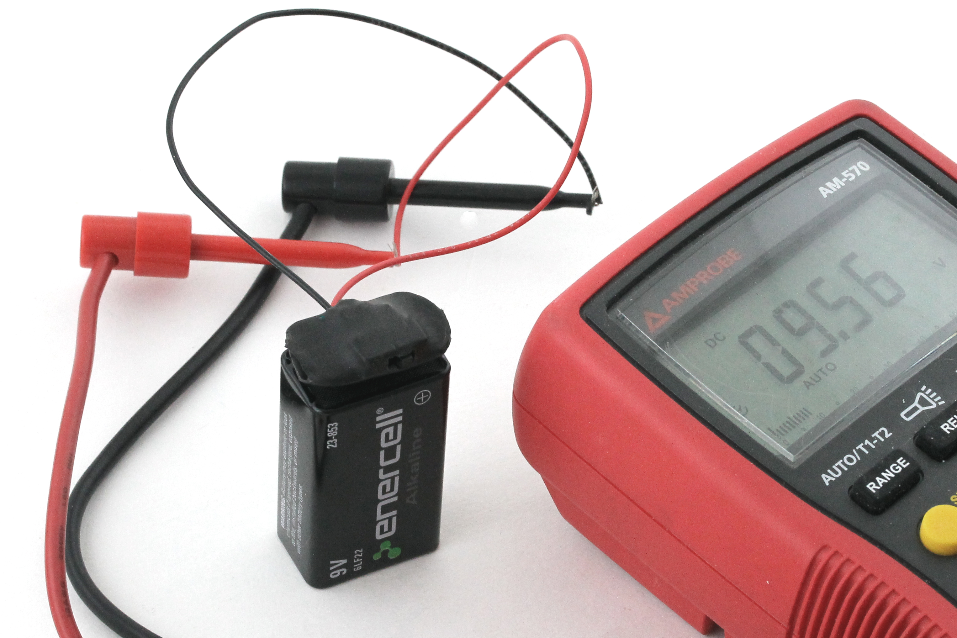
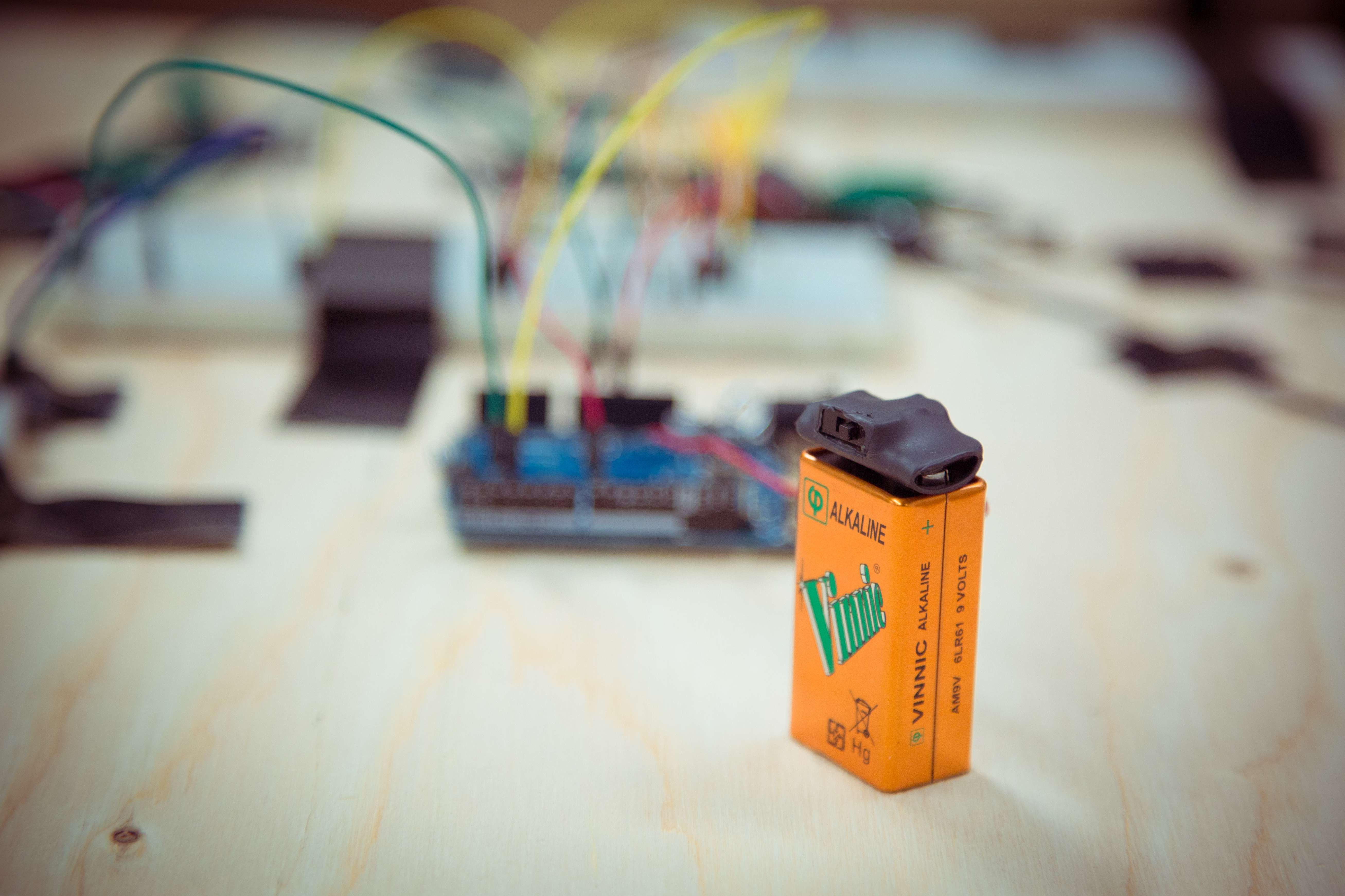
The first feature I wanted was a power switch, so I could turn the hovercraft on or off without having to clip and unclip the battery. Looking around my prototype for a convenient place to mount the switch, I realized that the battery clip itself presented the most minimal and elegant opportunity. I also immediately thought of a bunch of other projects — from breadboarding to BEAM robotics to Arduino — where a 9V battery clip with a built-in power switch could come in handy. But nobody seems to sell one. So I made my own — Das Neunvoltzensvitcher!

Project Steps

Dismantle the battery

Use the tip of your pliers to grab the metal casing of the battery at the seam. Squeeze hard and peel the casing away to expose the individual cells inside.

Pull away the tab at the end of the battery with the 2 snap terminals. It should be connected to the cells by a pair of riveted metal strips. Cut these with your scissors, leaving as much of each strip attached to the snap terminals as you can. Discard everything but the end of the battery with the snap terminals and their attached metal strips. Rotate the battery terminals in the panel so that the metal strips fold outward.

Drill a 1/8″ strain-relief hole, as shown, located halfway between the 2 terminals, in the long dimension, and halfway between the terminals’ centerline and the edge, in the short dimension.

Install the switch

Cut and strip both ends of two 6″ lengths of wire — one red and one black. Twist and tin all 4 stripped ends. Solder one end of the red wire to the switch center pin, and one end of the black wire to either of the outside pins. Insulate the center pin and solder joint with a short (~1cm) length of 2mm heat-shrink tubing. Tie a strain-relief knot in the 2 wires as close to the pins as possible.

Route the switch wires through the strain relief hole, starting from the side with the metal strips. Align the switch body with the long edge of the terminal tab opposite the hole, and glue in place with 5-minute epoxy. The switch lever should protrude past the edge of the terminal tab.

Solder the 2 outer switch pins (one with a black wire already soldered on) to the metal terminal strips. Verify that the circuit across the end of the leads closes with the switch in one position, and opens with it in the other, then fold the metal strips over to cover the solder joints.

Insulate and test

Cut a 1″ length of 12mm–14 mm heat-shrink tubing, then slice a ¼” slit in the middle of one edge as shown. Thread the wires from the switch into one end of the tubing and out the slit from the inside.

Continue sliding the battery tab into the open end of the tubing and work it over the entire assembly (switch, terminals, and all) with the wires poking out the side. Apply heat to shrink the tubing, then use a hobby knife to cut openings for the switch lever and the battery snaps.

Attach the clip to a 9V battery and use your voltmeter to verify that the ends of the leads read 7V–10V DC with the switch in one position, and 0V DC with it in the other.