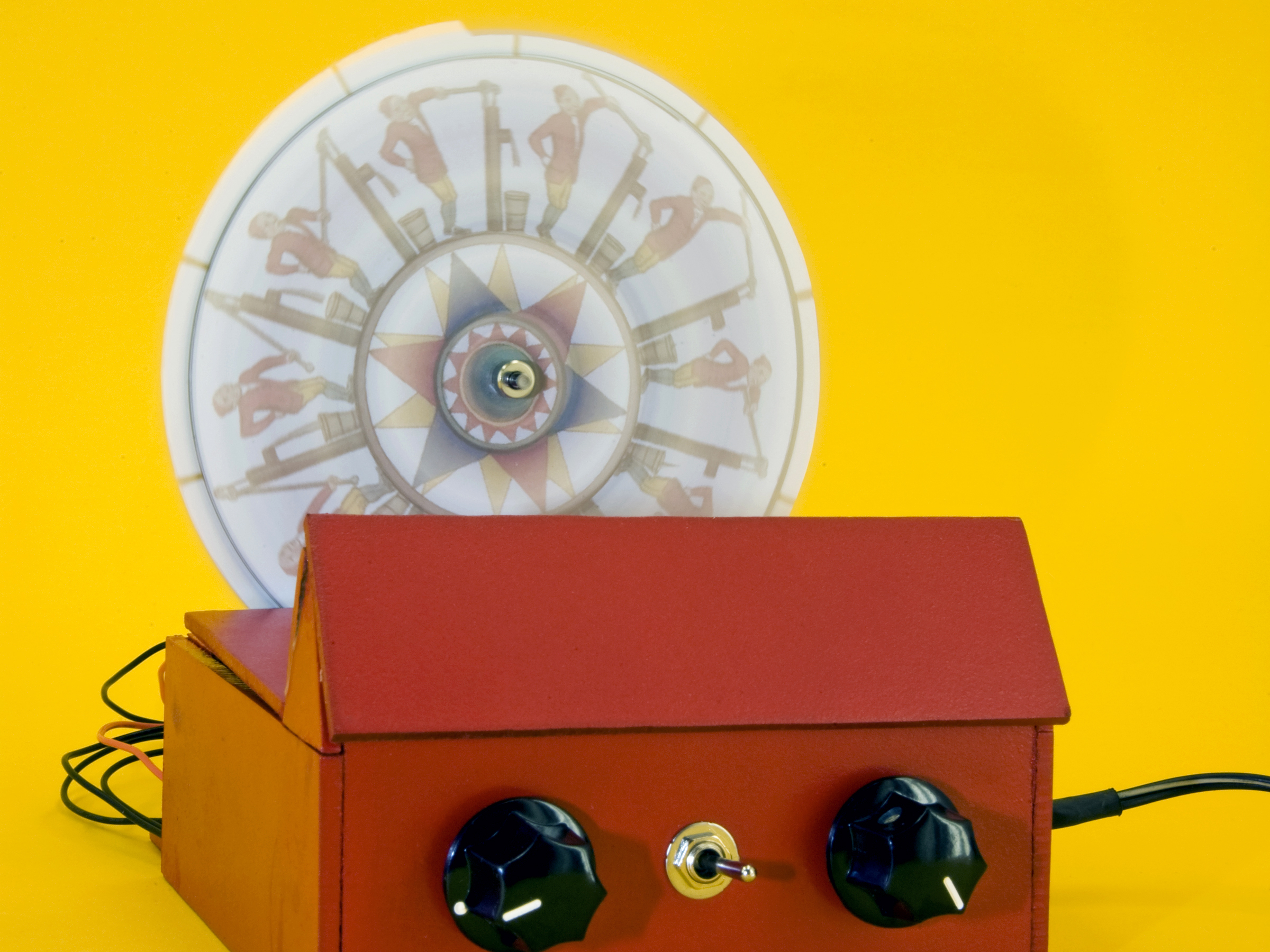
Motorize a phenakistoscope, a 19th-century parlor novelty that preceded motion pictures, and keep its frames synched to an LED strobe by using a sensor and an Arduino microcontroller.

Invented in 1832 by Joseph Plateau, this device creates a moving picture from a sequence of stills arranged on a spinning disk and viewed through strategically cut slits. It’s easy to see how this invention and others like it evolved into movies and television.

My 9-year-old daughter and I wanted to make something new with Lego Mindstorms. We had a strobe, and we thought of combining it with a spinning disk to create animation. But it was difficult attaching the disk to the Lego motor, and we couldn’t control the motor and strobe speeds precisely enough to get them to match. The project really came together once we started using a gearmotor to give the disk a smooth, finely controllable rotation speed.

With an adjustable-frequency strobe, we experimented with persistence of vision and sympathetic frequencies, and produced several interesting visual effects. Finally, using an Arduino, a simple C program, and a sensor, we automatically synchronized the strobe with the rotating disk. A switch toggles between manual and microcontroller strobe control.

Project Steps

Prepare the image disc and synchronization wheel.

Download and print a sample disk image and the templates in the documents area. Print the disk image in color, ideally on a laser printer so the colors won’t bleed if the disk gets wet.

Trim the disk image with scissors but don’t cut out the center hole. Glue it to the CD using spray adhesive. Let it dry for 30 minutes, then cut out the center hole with an X-Acto knife.

Cut out the sync wheel template but not the slits around its perimeter. Adjust a compass to the outside radius of the template and use it to draw a circle on the mat board. Then cut the circle out of the mat board.

Cutting mat board with scissors or an X-Acto knife can be difficult, but electric scissors make it easier. The circle doesn’t have to be perfect.

Tape the sync wheel template onto the mat board disk and use an X-Acto knife to cut the slits. Remove the template.

Cut the 2 smallest disks from the template out of mat board. The smaller one nests inside the CD’s hole and the larger one acts like a washer, reinforcing the image disk in back.

Build the stand and case.

Cut the paper stand and case templates, and spray-glue them to the hardboard sheet. Let the glue dry a minute before sticking the paper down, so it’s less permanent.

Cut out all the pieces following the templates. I started with a chop saw and finished with a razor saw. To cut the rectangular indentations (wire channels), use the razor saw to cut the sides, then score the top cut with an X-Acto knife and snap it off. Sand all cut edges smooth.

Mark and drill the holes for mounting the motor, IR emitter and sensor, and LED strobe. A brad-point bit will make this easier. I should have used (but didn’t) snap-in, panel-mount LED holders, which mount easily into ¼” holes.

Glue the pieces together to form the stand and case, using masking tape to hold everything together until it dries. Don’t glue the front panel cover (that comes later) or the top cover (which is never glued). Be sure the sides of the stand don’t protrude from the other segments, or you may have trouble inserting it into the case later. Let dry at least an hour.

Glue the stand into the back of the case. If it doesn’t fit, sand down any interference points. Let it dry.

Prepare the hardboard for painting by sanding it all over with medium-grit sandpaper, smoothing imperfections and softening corners. Finish with fine-grit paper, then paint. For bright colors, it helps to start with a primer coat of white acrylic latex. Don’t forget to sand and paint the front cover and top cover pieces.

Prepare the electronics components.

Cut all the wire segments and strip 1/3″ from both ends of each. You’ll need:

12″ pieces (14): red (6), black (6), orange, brown

6″ pieces (5): blue, yellow, purple, green, white

The power wires are red and black, and the others are the signal wires. If you don’t have enough colors, label the wires as you make the connections.

Solder leads to the two 5K pots, using 12″ red and black segments for the outside terminals (for positive and negative power), and 6″ unique colors for the signal pins in the middle — I used purple for motor and yellow for strobe. The red and black should run in opposite directions on the 2 pots.

When soldering wires to posts, first make a mechanical connection by wrapping the wire around the post, then solder the connection.

Solder leads to the IR emitter, which is the dark one in the emitter/detector pair. Solder a black wire to the shorter (–) leg of the emitter, and a 100Ω resistor connected out to a red wire to the longer (+) leg. Seal the connections with heat-shrink tubing by slipping pieces over and shrinking them with a heat gun or lighter.

Solder leads to the IR sensor. Solder a red wire to the short leg and put a 10K resistor between the black wire and the long leg. Also connect a green sensor wire between the negative lead and the resistor. Seal with heat-shrink.

Solder a white wire to the longer leg of the strobe LED and a black wire to the shorter leg.

Connect a red wire to one side of the toggle switch and a black wire to the other through the second 10K resistor. Connect a blue wire between the resistor and the switch. Solder the connections and seal with heat-shrink.

Solder the 12″ orange and brown wires to the motor terminals.

Make 2 terminal blocks to organize all circuit connections to positive and negative voltage. Cut a 12-post terminal strip in half, and use markers to color one side red and the other black. For each half, connect a matching lead, and jumper all of the remaining terminals using bare wire. Use a multimeter to confirm that there’s near-zero resistance between all terminals on each block.

Assemble the electronics.

Use two 2-56×¼” or similar small screws to mount the motor to the stand and attach a 1/8″ shaft collar to the motor shaft, spaced away from the motor a little so it doesn’t hit the mounting screws when it rotates. Verify that the collar is tight and that the motor turns freely.

Mount the IR emitter and sensor facing each other in the stand. I decided to put the emitter in back because it’s always on and it connects only to the red/black terminal blocks.

Mount the pots and switch onto the front panel using the included hardware. If necessary, trim the pot shafts to fit the knobs. Install the knobs, and clip any alignment tabs to enable the pots to sit flush against the panel.

Use double-stick foam tape to mount the terminal strips to the floor of the case in back.

Assemble the Arduino and motor controller boards following the included instructions. On the motor controller, you can use the regular Motors header, but substitute the longer, stackable headers, sold separately, for the Encoder and Power headers. Finally, plug the motor controller board onto the Arduino, making sure to properly line up the pins.

Download the Autophenakistoscope source code from the documents section, then compile and upload to your Arduino.

Make the following connections to the Arduino board:

Yellow/strobe pot: Analog pin 5

Purple/motor pot: Analog pin 0

Green/IR transistor: Digital pin 2

White/strobe LED: Digital pin 13 (the LED hangs free, not mounted yet)

Connections continued:

Brown and orange/motor: Shield motor B (upper 2 terminals on the Motors header)

Blue/mode switch: Digital pin 3

Red/positive terminal block: 5V Power

Black/negative terminal block: Ground

Run all the red/positive and black/negative leads through the wire channel and connect them to corresponding terminal strips. You can tidy up the wiring with small zip ties.

Final assembly and testing.

Cut holes in the center of the sync wheel and the 2 smaller cardboard disks to fit snugly over the motor shaft. Slip the middle-sized disk over the shaft, then the sync wheel (be careful not to bend it), and finally the smallest disk.

Slip the CD onto the motor shaft, facing front. Fit it around the smallest cardboard disk, and secure it so it won’t slip. I used another knob to hold it, but you can also use a shaft collar and washer. I drilled the knob to let the long shaft pass through, but you can also cut the shaft.

It’s time to run some tests. Connect power to the Arduino, and you should see the strobe flash and the motor spin up to about half power. The strobe should synchronize to the wheel; dim the lights and shine the LED on the image disk to check. Magic!

If it behaves the opposite way (motor goes full speed when turned down low), reverse the Arduino connections for the 2 pots. If it doesn’t work, double-check all your connections to the Arduino, and if you still have problems, see my troubleshooting guide at retrotronics.com/autophenakistoscope.

Once your Autophenakistoscope works, close it up by mounting the white strobe LED to the front panel, gluing on the front panel, and slipping the cover on top. Phenakistastic!

Design your own image disks

To generate the sample image disks, I took some vintage animation loops and cleaned them up using GIMP software (http://gimp.org). To make the process easier, I wrote a web application, http://www.retro-tronics.com/APKS/disk.p…, that you can use to make ’scope-ready disks from uploaded photos.

Conclusion

Time and motion studies

Just like the movies, the Autophenakistoscope works best in low light. Dim the lights and plug it in. It first spins up the motor to half power, flashes the LED a few times, then starts reading inputs from the potentiometers. When the motor pot is turned all the way down, the motor should be off. When the strobe pot is all the way down, it should flash about once per second (1Hz).

Adjust the motor and the flash frequency to a moderate level. Toggle the mode switch once or twice to figure out which is which — in automatic mode, the image should stabilize; in manual mode, it will wander or not be legible.

It’s time to experiment. Adjust the knobs and you’ll see that multiple frequency combinations can produce smooth moving images. It’s also possible to freeze the image by adjusting the rotational frequency to match the strobe frequency.

When I first built this project, I noticed that the image can “roll” just like it used to on the old black-and-white TV when I was a kid. It turns out that this is a completely analogous result.

Another interesting experiment is to videotape the Autophenakistoscope. You’ll find that the frequencies of the strobe can coincide with the scanning frequency of your recorder. If you get it just right, the scope will appear to be dark in your video when it looks well-lit to your eyes.

Mechanical television

I discovered the phenakistoscope while investigating mechanical television. Mechanical television is actually very simple, but impractical except for very small screens. The scan lines are generated with a perforated spinning disk known as a Nipkow disk.

In the 1920s, television started with 24- or 32-line screens, and there were regular mechanical television broadcasts decades before Milton Berle showed his face in our (grandparents’) living rooms.

A 420-line spinning disk is another story; it would have to spin at very high frequencies to fully paint the screen at a rate that would satisfy the eye. But the Autophenakistoscope would make a great platform for a modern, experimental mechanical television. I’d also like to see it scaled up.

This project first appeared in MAKE Volume 20, page 100.