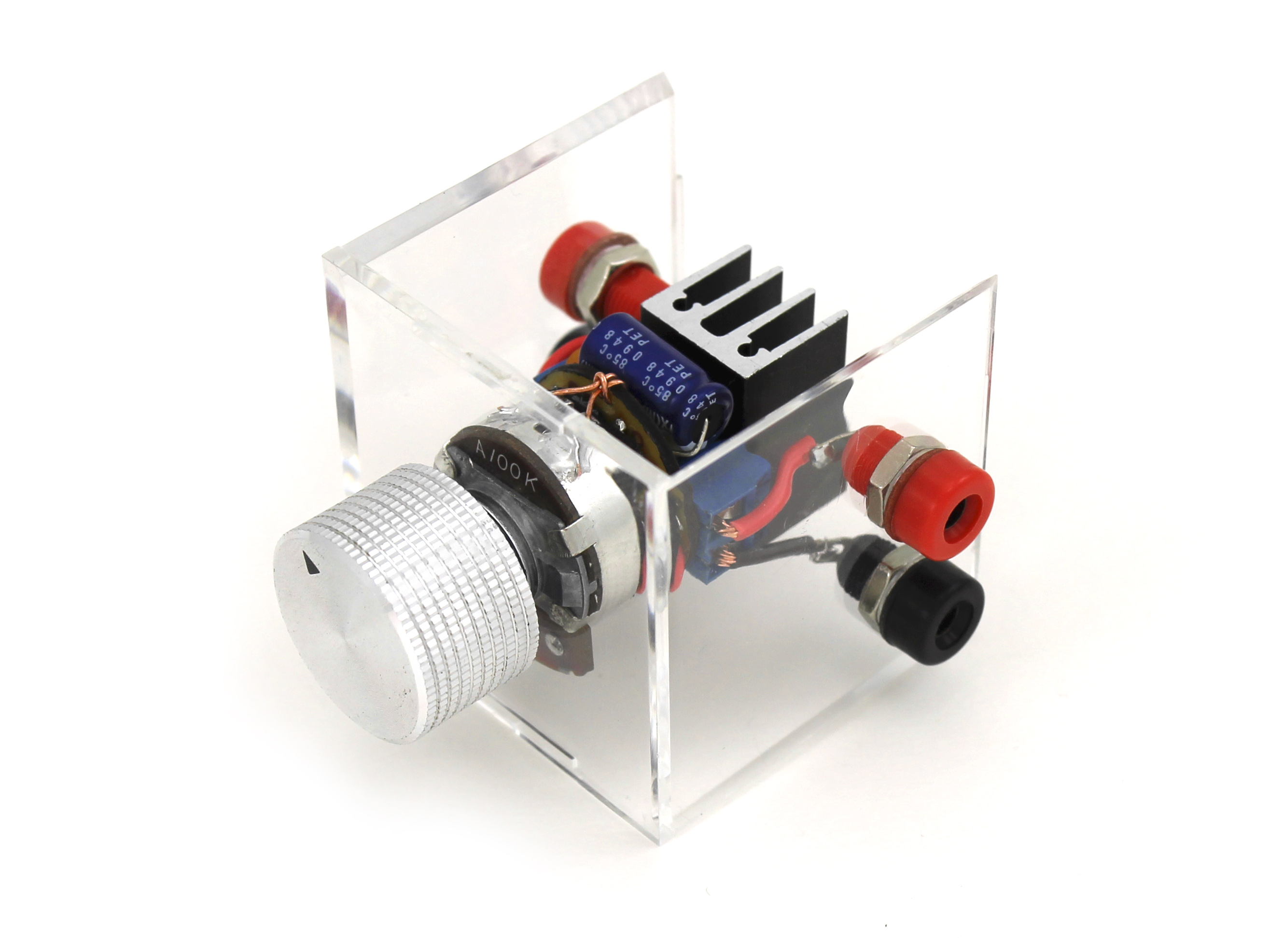
One of the most common problems in building small robots and other electromechanical projects is that off-the-shelf DC motors just run too fast for many applications. Sometimes a mechanical fix like a gear or capstan drive is the solution, but many times you’ll want to skip the additional noise, space, and precise construction that mechanical drive-trains entail. In these cases, a “direct-drive” arrangement, in which the motor shaft is directly coupled to the load it turns, is likely best. And you’ll find yourself in need of an electronic speed controller.
Enter the Dial-a-Speed, a DIY one-size-fits-most speed controller for small DC motors. It’s built in a compact physical package around a full-size potentiometer, includes built-in back-EMF protection, and has on-board screw terminals for easy motor and power connection. The Dial-a-Speed accepts 5-12V DC, can be easily panel-mounted in most enclosures, and will provide effective speed control of any continuous-rotation motor or fan in the RadioShack catalog as of this writing.
| PRODUCT | VOLTS (DC) | MAX (RPM) | MIN (RPM) |
 9-18V Hobby Motor 9-18V Hobby Motor |
9 / 12 | 11,030 / 14,300 | 176 / 795 |
 6V Micro Motor 6V Micro Motor |
6 | 15,500 | 1,191 |
 7.5V Micro Motor 7.5V Micro Motor |
7.5 | 15,900 | 1,259 |
 9V Micro Motor 9V Micro Motor |
9 | 20,200 | 2,641 |
 1.5–3V Gear Motor 1.5–3V Gear Motor |
5* | 17,900 | 2,462 |
 1.5–3V Hobby Motor 1.5–3V Hobby Motor |
5* | 16,700 | 2,798 |
 12V Micro Fan 12V Micro Fan |
12 | 6,640 | 115 |
 12V 3″ Fan 12V 3″ Fan |
12 | 2,432 | 130 |
 12V 4″ Fan 12V 4″ Fan |
12 | 2,611 | 100 |
How Does it Work?
This is a pulse-width modulation (PWM) speed controller, using a 555 timer IC wired in astable mode to control an N-channel power-enhancement MOSFET that actually switches the motor on and off. It is based on a circuit posted by Rick Bickle of the Dallas Personal Robotics Group, with minor modifications for use in a shared power supply configuration.
What does all that mean? Basically, instead of a continuous stream of current, the circuit sends power to the motor in little pulses, at a more-or-less constant frequency (around 50 times a second). The length of these pulses (aka their width) can be changed (aka modulated), which causes the speed at which the motor turns to change, too. The longer/wider the pulses, the faster the motor goes.

If you were to plot the voltage going to the motor against time, perhaps using an oscilloscope, it would look more-or-less like a square wave, illustrated above. When describing square waves, the amount of time spent in the “high” voltage state is called the mark time, and the amount of time spent “low” the space time. The duty cycle is a percentage expressing how much of each wave cycle is “mark time.” For example, if your pulses are coming 1 a second, and your mark time is 0.6 seconds, then the duty cycle is 60%. This circuit is cleverly designed to offer a wide range of control, and can produce square waves with duty cycles ranging from less than 5% to more than 95%, depending on where you set the dial.


