I’ve been making electronic musical instruments for a while now, and every step of the way they get more complicated, and harder to produce. Taking a break from the more intense synths, I wanted something simple, easy, and fun to build.

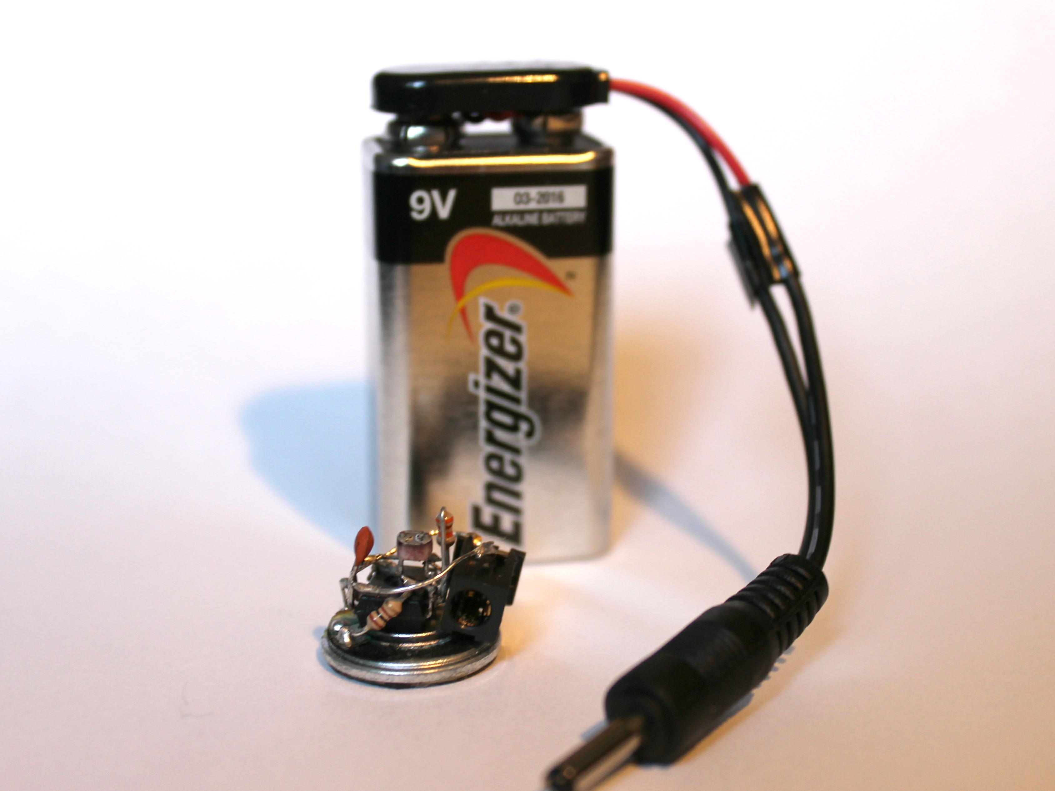
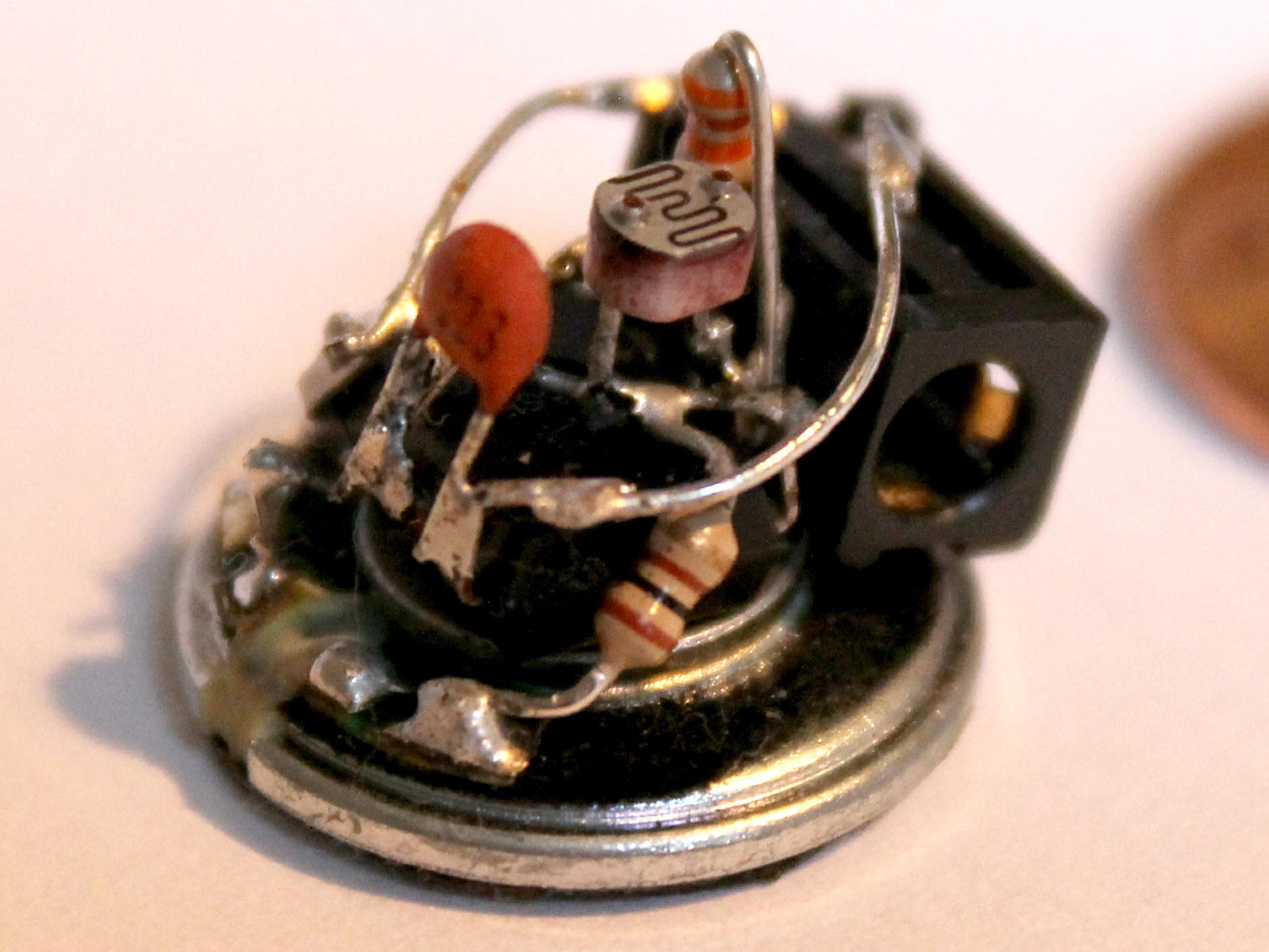
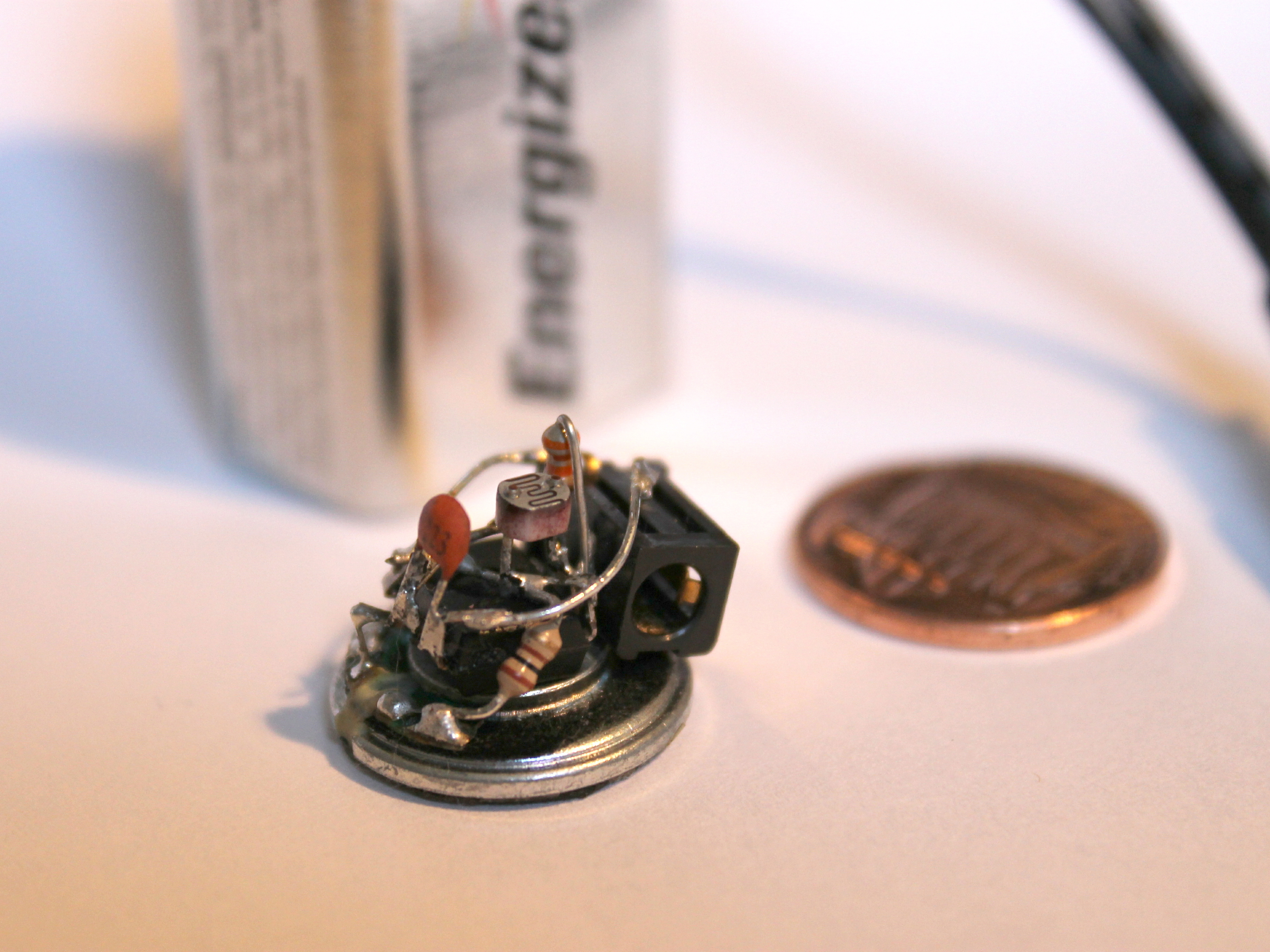
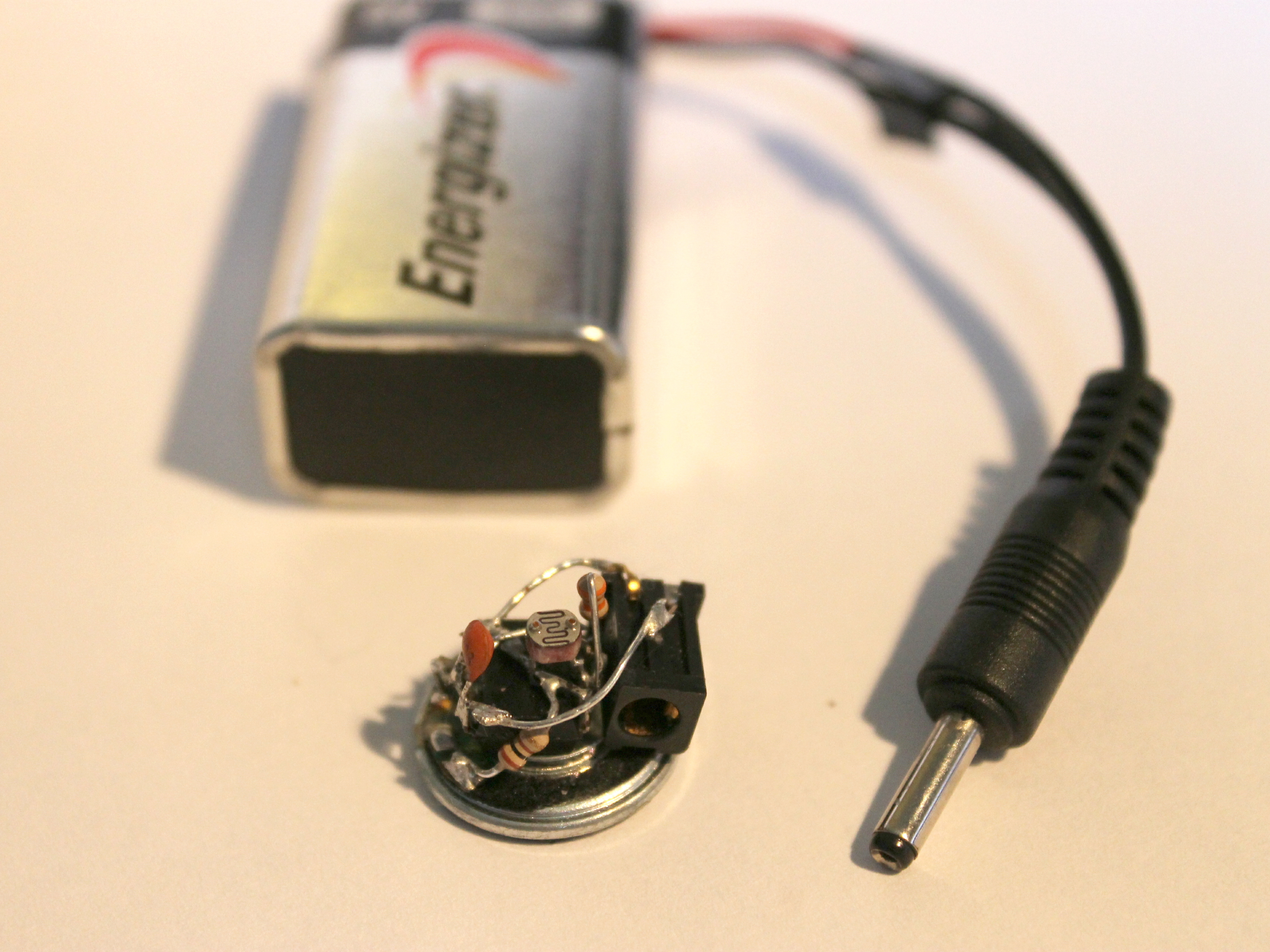
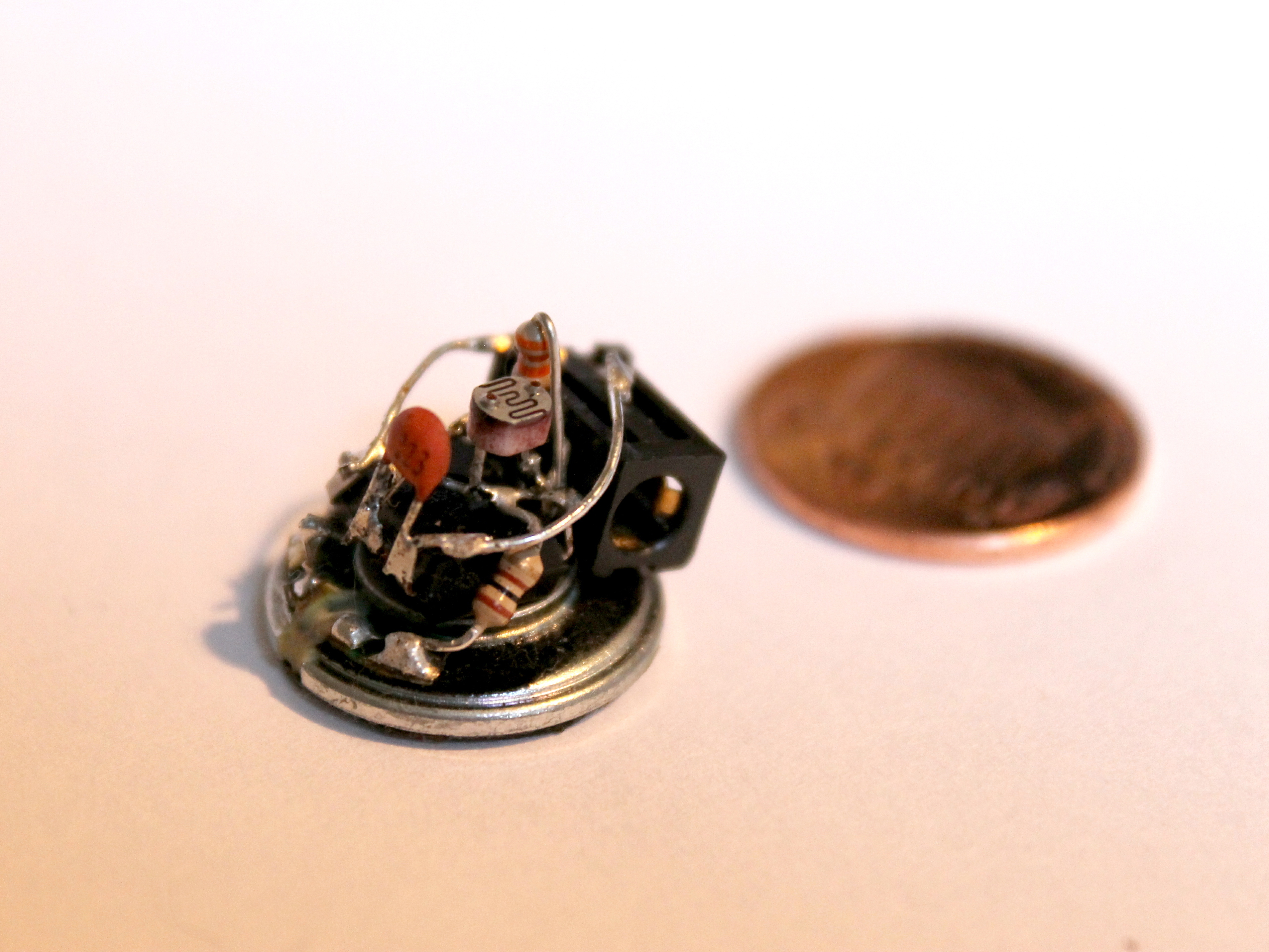
Today I made a simple 555 timer synth with a twist – it’s smaller than a penny! There’s no SMD soldering or programming, and the parts are minimal. It’s great for a project to build over an afternoon.

Project Steps

Be careful when making this project. You will have to make all soldering connections quickly to avoid frying the chip. If you have spent over a few seconds trying making a connection, but still can’t make one, wait a bit before attepting to solder again. DON’T OVERHEAT THE CHIP!

The 555 timer leads will snap off EASILY if you bend them too many times. Only make 1-4 bends total on each lead (i.e., don’t wiggle the leads back and forth for the perfect angle). I ruined 2 555 timers this way.

Place your 555 timer upside down on your workspace (“dead bug” mode). It will be this way the whole build. Note that since the chip is turned over, the pin numbers are mirrored, something that can easily be mistaken later on.

Bend pins 4 and 8 toward each other over the chip. Put these as close to the chip as possible.

Bend pin 3 reaching out and down toward the speaker. Don’t solder to the speaker just yet though.

If you want, you may also clip off pin 5 to avoid extra unwanted connections. We won’t be soldering anything to this lead.

Solder your lead clips (maybe from the resistor or capacitor leads?) as shown. Put one from pin 4 to pin 8 and one from pin 2 to pin 6.

Also solder in the 100-ohm resistor to the wire connecting pins 4 and 8. Bend this resistor over the chip and to the side.

Now you can solder in the speaker if you choose to steady the chip when soldering. It helps a lot. :)

Now it’s time to insert more components. Solder the 0.022 uF cap from pin 1 to pin 2. Then solder the photoresistor from pin 7 to pin 8.

When you solder the 33KΩ resistor, it’s easiest to stand the resistor up. Fold one lead over the side of the resistor. Then solder it to pins 6 and 7.

If you didn’t before, now solder the chip to the speaker.

Time to make the power supply. Cut the male power connector from your cell phone charger or such and strip the leads. Take your 9V battery clip and solder the red to one lead and black to the other. Polarity doesn’t matter for now.

Cover your connections in electrical tape and connect clip to battery.

You’re almost done! Connect your power supply to the female power connector and use a multimeter to determine the polarity of the outputs.

Solder the positive connection to pin 4 and the negative lead to pin 1 using lead clips.

Hooray! Enjoy your new musical instument! When you plug it in to the 9V battery supply, it whould start right away and vary in tone with the light you give it.

If it doesn’t work, check all your connections. Mine didn’t work at first, so I resoldered the cap even though it looked fine. Now it works like a charm!