[youtube:http://youtu.be/ijPXO6MgpwU]

You may be familiar with the useless machine. This is a machine whose only function is to turn itself off. When you flip the power switch to turn it on, an arm pops out of the box and turns the power switch back off.

I love the hilarious absurdity of this project, so I decided to make some “useless” devices of my own. In this project, I am going to share with you how to make a “Useless Candle.” Whenever you light this candle, it automatically blows itself out.

This is done with a simple light sensor and a small air pump. When the sensor detects the increased light from the candle being lit, it turns on an air pump. The air pump pushes air through a tube that is mounted to the candle holder and blows the candle out.

Project Steps

The Control Circuit

The control circuit for this project is built around a 555 timer IC. When light shines on the CdS photoresistor, the voltage at pin 2 drops below the trigger threshold. This sets the output at pin 3 HIGH and activates a power transistor. The power transistor then turns on the relay. After a short delay, the system resets itself and the output is turned off.

The two capacitors are included to add a delay when turning the output on and off. The 100kohm resistor and the capacitor connected to pin 2 determine the delay in turning the output on. The fixed 10kohm resistor and the capacitor attached to pin 6 determine the delay in turning the output off. To increase either delay, you can increase the values of the resistors or the capacitors. To decrease the delays, you can decrease the values of the resistors or the capacitors. The power transistor is included so that you can activate relays that may exceed the power rating of the timer IC (200mA). The sensitivity of the sensor is set by adjusting the 10kohm variable resistor.

Select a Power Supply for the Control Circuit

To power the control circuit, I used a 5V USB charger. I chose this because the relay needs a 5V signal be triggered. The control circuit can run on other voltages, so you could use a generic DC power supply or battery pack to power the control circuit. You would just need a 5V voltage regulator for the relay. Alternatively, you could use a relay with a different voltage rating.

Prototype the Control Circuit on a Breadboard

It is always a good idea to prototype your circuit on a breadboard before soldering it together. Here, a simple LED can be used to indicate when the output is on. You will probably need to adjust the sensitivity of the sensor to match the lighting of the room. To do this, adjust the setting of the variable resistor.

Solder the Control Circuit onto Printed Circuit Boards

Once your circuit is working properly, you are ready to solder it onto printed circuit boards. Before soldering on the components, check to make sure that the board will fit in your housing. In my case, the circuit board was too big, so I trimmed the sides a little.

In the finished setup, the light sensor and the relay circuit will be connected to the control circuit with long extension wires. The final setup will look better if most of the electronics are hidden from view.

Assemble the Relay Circuit

The relay that I used is a simple “single pole, single throw” relay. Two terminals are connected to the coils and the other two terminals are connected to the switch. The coil terminals are connected to the output of the control circuit. A diode is also connected to the terminals of the coil with the cathode on the positive side and the anode on the negative side. This diode acts as a suppression diode (also called a flyback diode). It helps to protect the circuit from voltage spikes that are created when the relay turns off.

In order to turn the air pump on and off, we need to connect it to the switch terminals of the relay. To do this you can cut one of the two wires on the pump’s power cord and connect the two cut ends to opposite terminals on the relay. When the relay is turned on, the two wires will be connected and power will be supplied to the pump.

If you don’t want to cut into the pump’s power cord, you can get a cheap extension cord and make the connection with those wires instead. Then, just plug the extension cord into the wall outlet and plug the pump into the extension cord.

Because you are working with AC power, use great caution in the assembly process and make sure that all the connections are properly insulated.

Mount the Circuit Boards into Insulated Project Enclosures

​Now that you have your circuits built, you need to find a good housing for them. The relay circuit uses 120VAC. It is very important to keep its contacts insulated. I recommend a basic plastic project enclosure.

Use a knife to cut slots in the sides for the wires. It may also be a good idea to tape or hot glue the circuit board to the inside of the housing. That way it won’t bang around and get beat up if the enclosure is moved.

Find or Make a Candle Holder

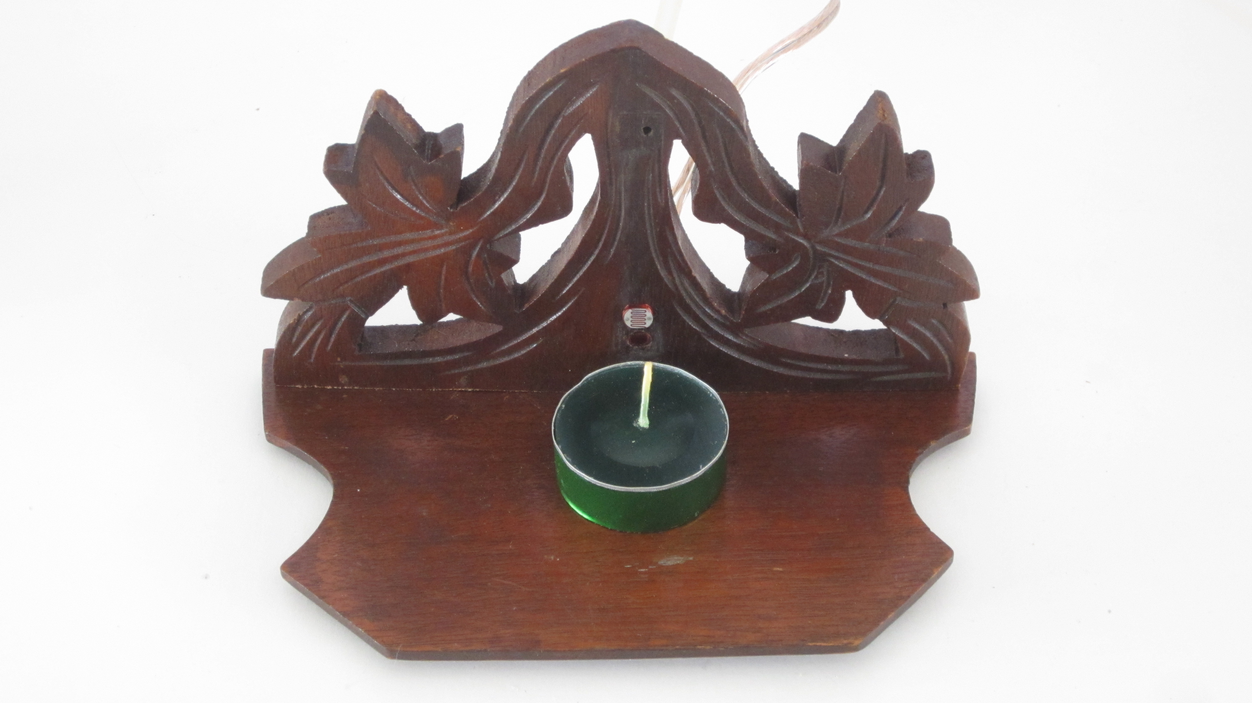
We need some way of mounting the air hose and the light sensor close to the candle. The easiest way to do this is to attach them to a candle holder or stand with a back plate. You can either buy one or make your own.

I chose a wooden candle stand because wood is very easy to drill and it is thick enough to easily mount the parts without glue. But always be aware of any potential fire risks. Keep the fire a good distance away from any flammable surfaces.

Drill Holes for the Air Hose and the Light Sensor

In order to mount the parts to the candle stand, you need to drill holes for them. First hold the candle up to the back plate and mark where the top of the candle lines up.

Then mark a point on the board that is about 1/8″ to 1/4″ (3mm to 6mm) above the top of the candle. This is where the air hose will be mounted. Drill a hole at this point that is just big enough for the air hose to fit firmly in place.

Next, drill two small holes about 1/4″ (6mm) above the first hole for the leads of the light sensor.

Color the Edges of the Air Tubing and the Light Sensor (Optional)

If the tubing and the light sensor don’t match the color of the candle stand, you can use a marker to color the edges so that it blends in better.

Mount the Air Hose and the Light Sensor to the Candle Stand

Now it is time to hook everything up to the candle stand. First connect the wires from the control circuit to the leads of the photoresistor. I recommend insulating each connection with heat shrink tubing. Then insert the air hose into the hole in the back of the stand and connect the other end to the air pump.

Try Out Your Useless Candle

Now your “Useless Candle” is complete. Set a candle on the stand in front of the sensor. Then light it. After a short delay, the air pump will turn on and blow out the candle. If you try to relight the candle, it will just blow itself out again.

I designed the circuit in such a way that the faster, you try to relight the candle, the faster it will be blown out. So if you just sit there constantly trying to light the candle, it may start blowing out the match/lighter before you can even get the candle lit. I thought that this made it a little funnier.