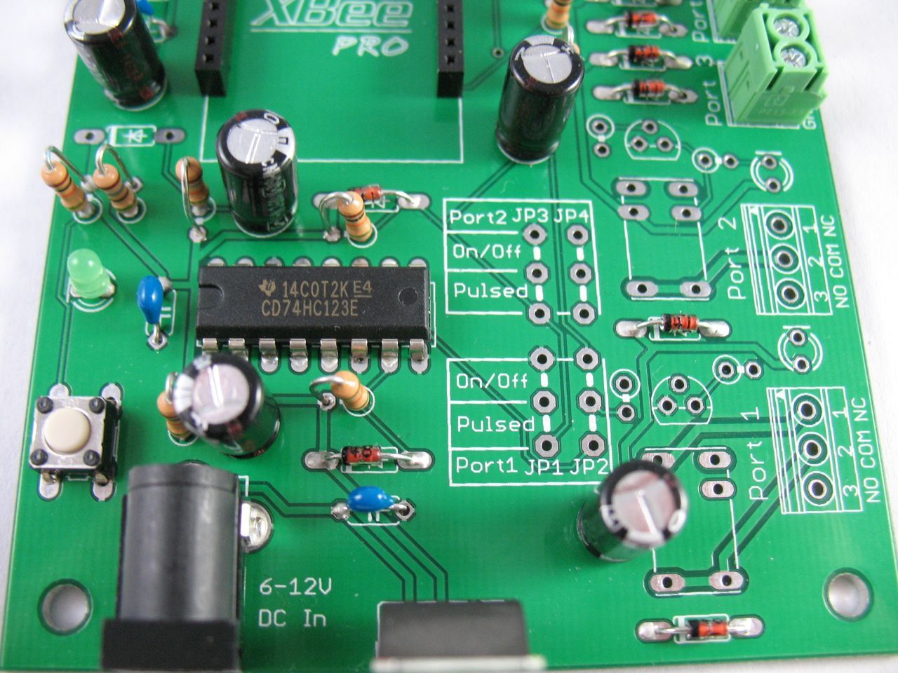
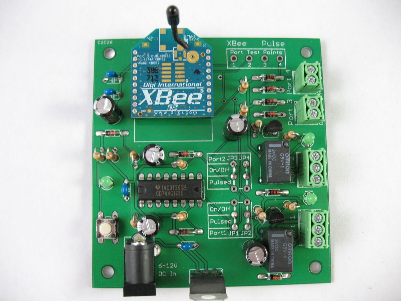
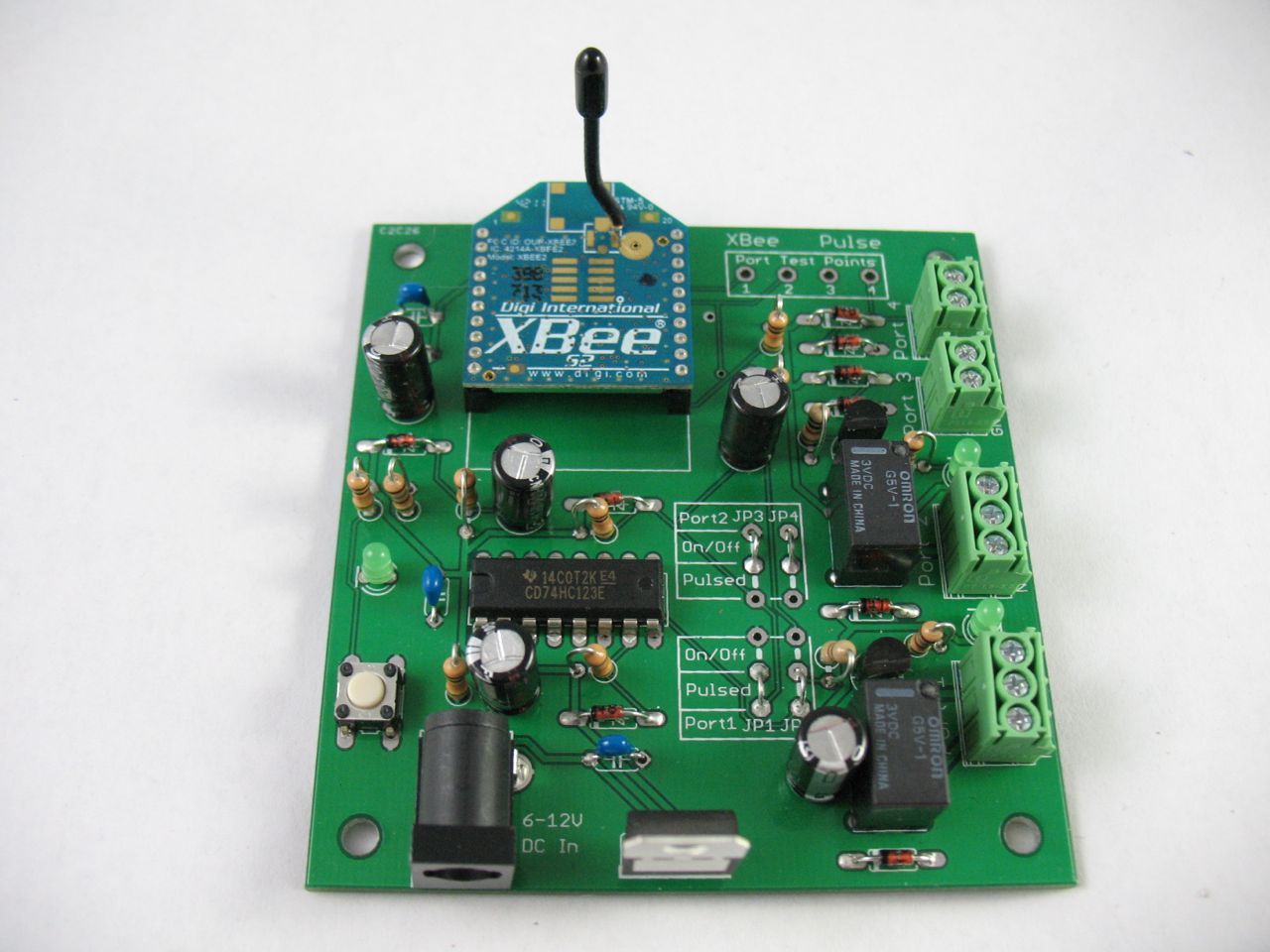
We’re going to lead you through step-by-step instructions to build a prototype XBee Pulse I/O board on a PCB. This board can be used to automate many things around a home and control them remotely. This design is featured in Make Vol. 30 and is used to connect a garage door opener to a mobile phone.

What will the next generation of Make: look like? We’re inviting you to shape the future by investing in Make:. By becoming an investor, you help decide what’s next. The future of Make: is in your hands. Learn More.

Project Steps

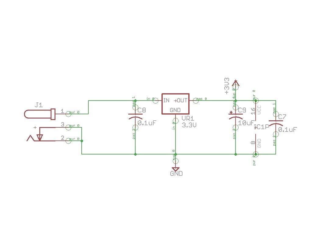
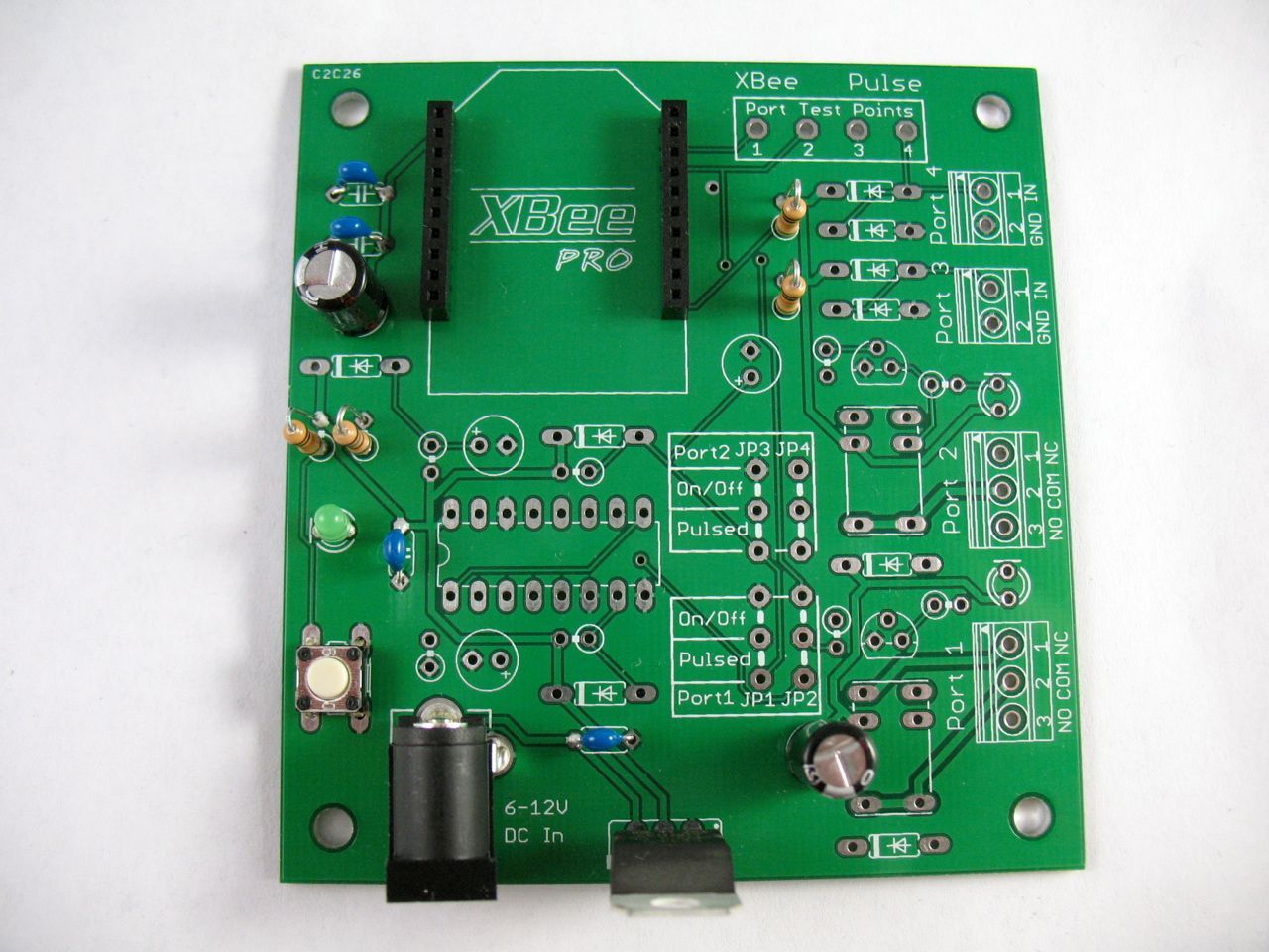
Assembly here begins with the power circuit. (You could choose to go in a different order and things would still work fine of course.)

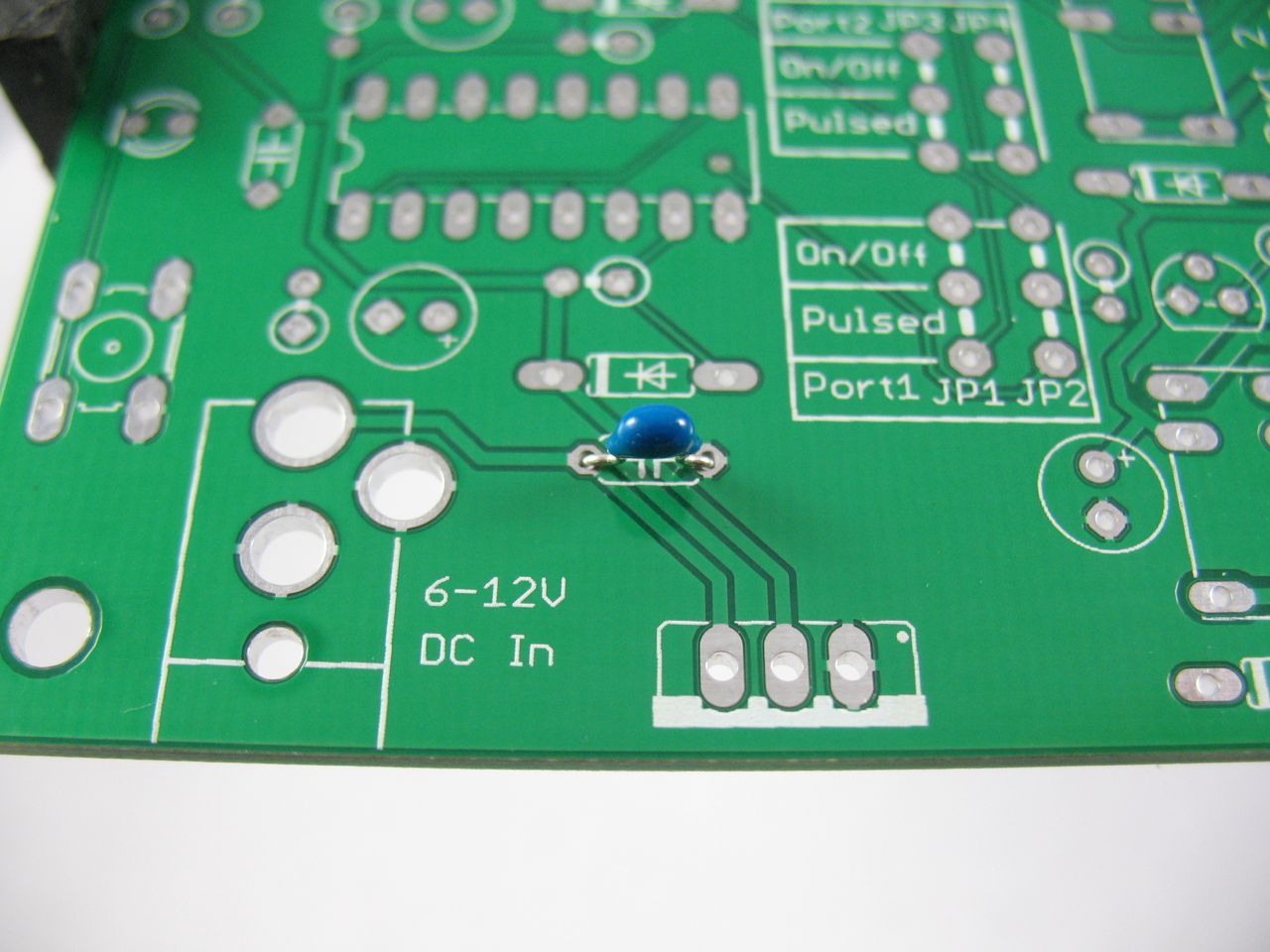
Place the 0.1uF capacitor C8 into the marked space on the printed circuit board (PCB). If you look closely the capacitor has a little “104” written on it.

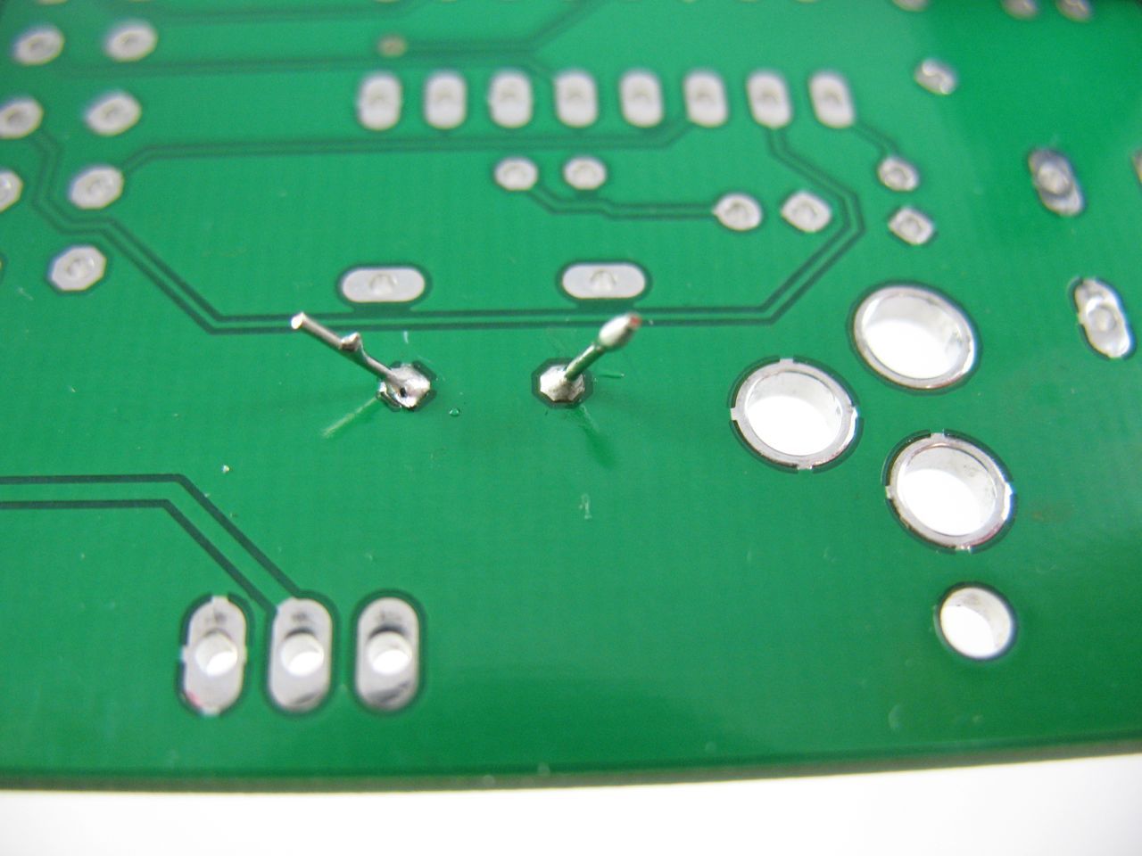
Turn the board over and solder each leg.

Trim the legs with snips so that they are fairly close to the board, but still stick up out of the solder “cones.”

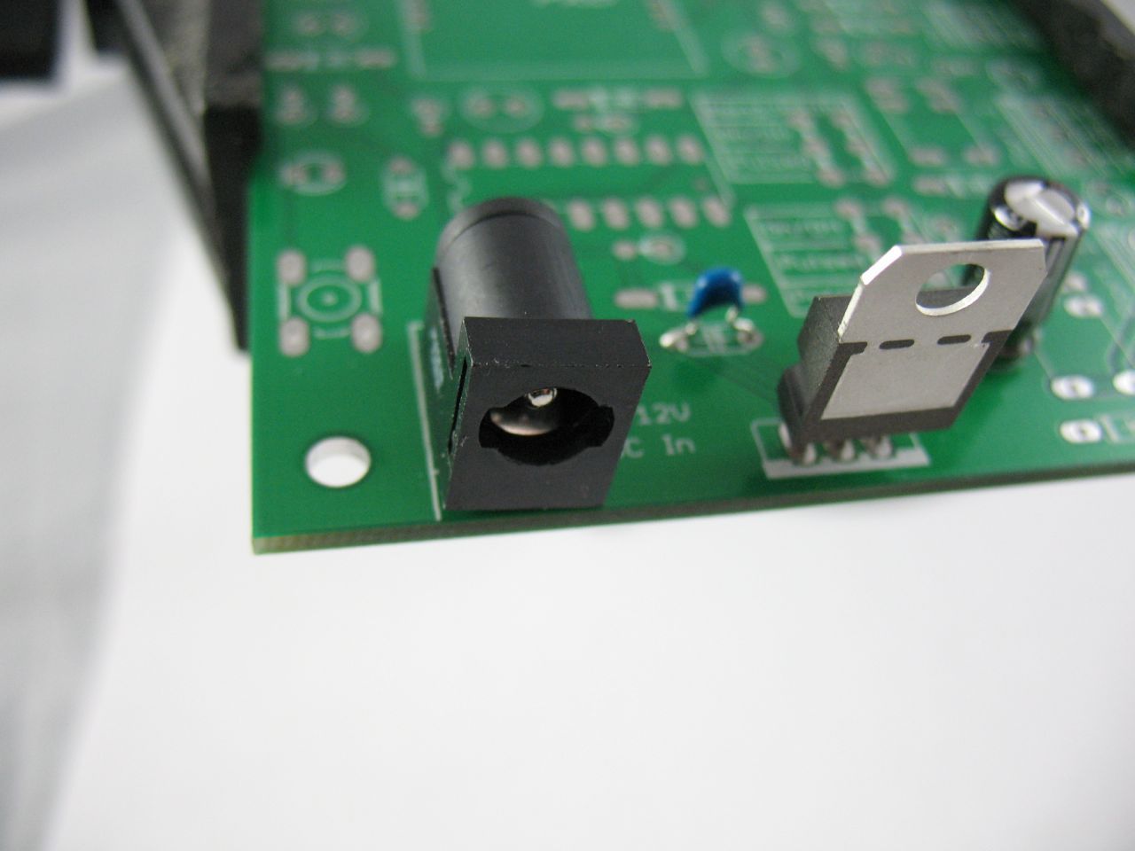
Continue by soldering the power jack (J1) with plenty of solder. It’s fine to fill the holes to give it mechanical support.

Next, place a 0.1µF capacitor in C7, solder it and clip the legs.

Carefully orient a 10µF capacitor in C9 so that the longer, positive leg goes into the + hole and the shorter, negative leg (marked with a silver stripe on the side) goes into the other hole. Solder and snip as before.

Finally, place the 3.3-volt regulator in VR1, oriented so that the metal heatsink portion is facing toward the edge of the board as shown. Solder and snip.

Assembly continues by creating the circuit for the XBee. Set aside your XBee module for now; we’ll use it later.

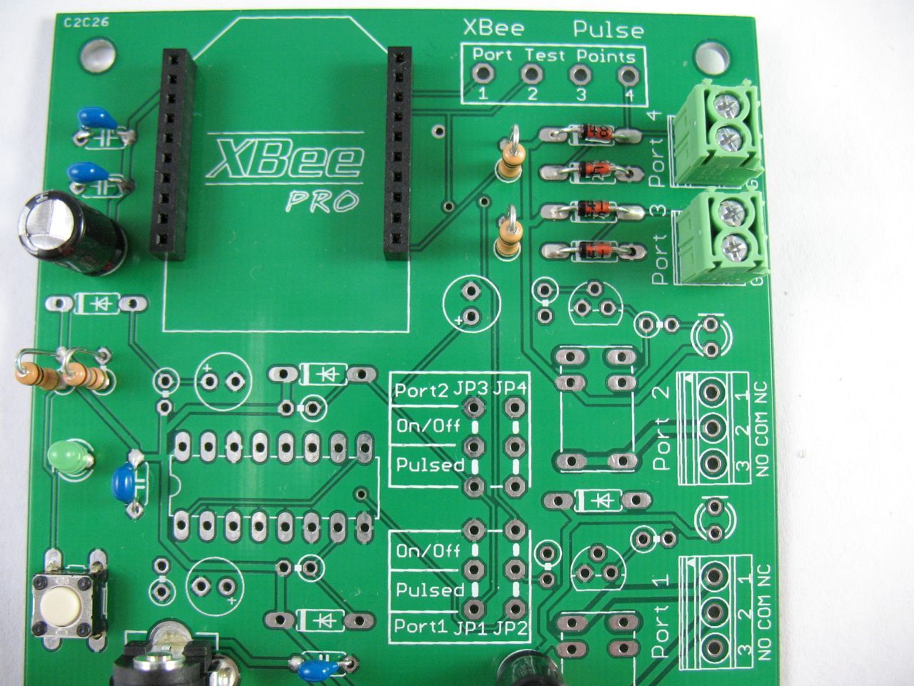
Solder the two sets of female headers for the XBee into place as shown. These will allow your radio to be removed for reprogramming if desired.

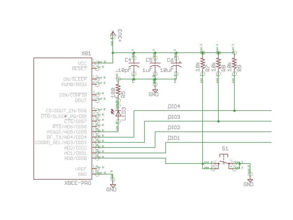
Next solder three 10K-ohm resistors to R7, R8 and R9. The resistor colors are brown, black, orange, gold. Bend one leg all the way over so the resistors can be soldered in upright as shown. Trim the legs.

Solder a 180-ohm (NOT 180K!) to R5 as above. The resistor colors are brown, grey, brown, gold.

Snap the tactile switch into S1 and solder all four legs. This switch is our network-commissioning button and will let us easily associate and test our XBee’s connection to our network.

Orient one of the green LEDs in the LED3 position so that its short, negative leg is beside the “|” line on the board. For this LED the shorter leg will be by the board’s edge. Solder and snip.

Solder a 10pF (NOT 10µF!) capacitor into C4 and a 1µF capacitor into C5. Solder a 10µF capacitor into C6, taking care to orient the longer leg so it is in the “+” hole and the shorter, silver striped negative leg in the other hole.

Orient four diodes so that the black stripe is to the left as shown, matching the markings on the board, then solder into D6, D7, D8 and D9. Finally, place the two terminal blocks into X3 and X4 so that the holes face the edge of the board and solder them in place.
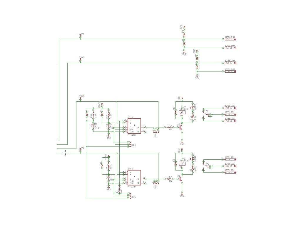
Now we’re going to set up the pulse-timer circuit. Insert the 74HC123 timer chip IC1 (datasheet) with the notch on one side of the chip matching the notch outlined on the board. Make sure you orient it the right way! The notch will be on the left as shown in the photo. Double-check, then solder it in place.

Place diodes in D2, D3, D4 and D5, making sure to orient them so the black stripe on one end matches the markings on the board. Solder and snip.

Place a 10K-ohm (brown, black, orange, gold) in R1 and R11, folding one leg over so it can stand upright. Solder and snip.

Place an 18K-ohm (brown, gray, orange, gold) in R4 and R12 as above.

Solder a 47uF capacitor into C2, making sure that the longer leg goes into the hole marked “+”.

Orient 22µF capacitors so that the longer leg matches the “+” sign in C1 and C3. Note that they will face opposite directions on the board! Double-check, then solder and snip.

We’ll continue now by completing the output circuits. Put the two NPN 2N3904 transistors (datasheet) into T1 and T2. Orient the flat side to face forward, as shown in the outline on the board. You will need to bend the middle leg back a bit to match the holes. Solder and snip.

Solder two 1K-ohm (brown, black, red, gold) resistors into R2 and R6 as before. Then solder two 180-ohm resistors (brown, gray, brown, gold) into R3 and R10 in the same way.

Orient the two remaining green LEDs in LED1 and LED2 so that the shorter leg matches the “|” line on the board. Solder and snip.

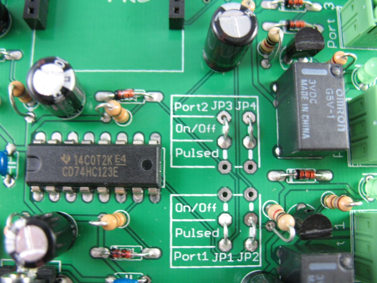
By this time you’ve created a lot of snipped wire leads. We’re going to recycle four of them into use as jumper connections! Bend your leads (or any spare hookup wire) into a U-shape. For JP1 and JP2 we’ll be using Pulse mode so connect the two bottom to middle holes as shown. For JP3 and JP4 we’ll leave it in on/off mode, so connect the two top to middle holes as detailed in the photo. Solder into place and snip. If you ever want to change the modes, you can desolder these connections (or just cut them) and rewire to the other mode.

Place the two relays (datasheet) into K1 and K2. Solder all six legs of each into place.

You have one diode left. It goes into D1. Orient it to match the board outline, solder and snip.

Finally, place the three-port terminal blocks into Port1 and Port2. Orient them so the holes face the edge of the board and solder them into place.

Congratulations! You’ve finished building the XBee Pulse I/O on a Printed Circuit Board!