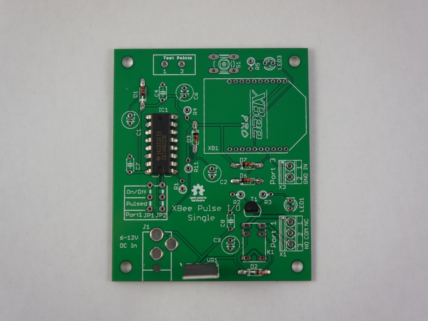
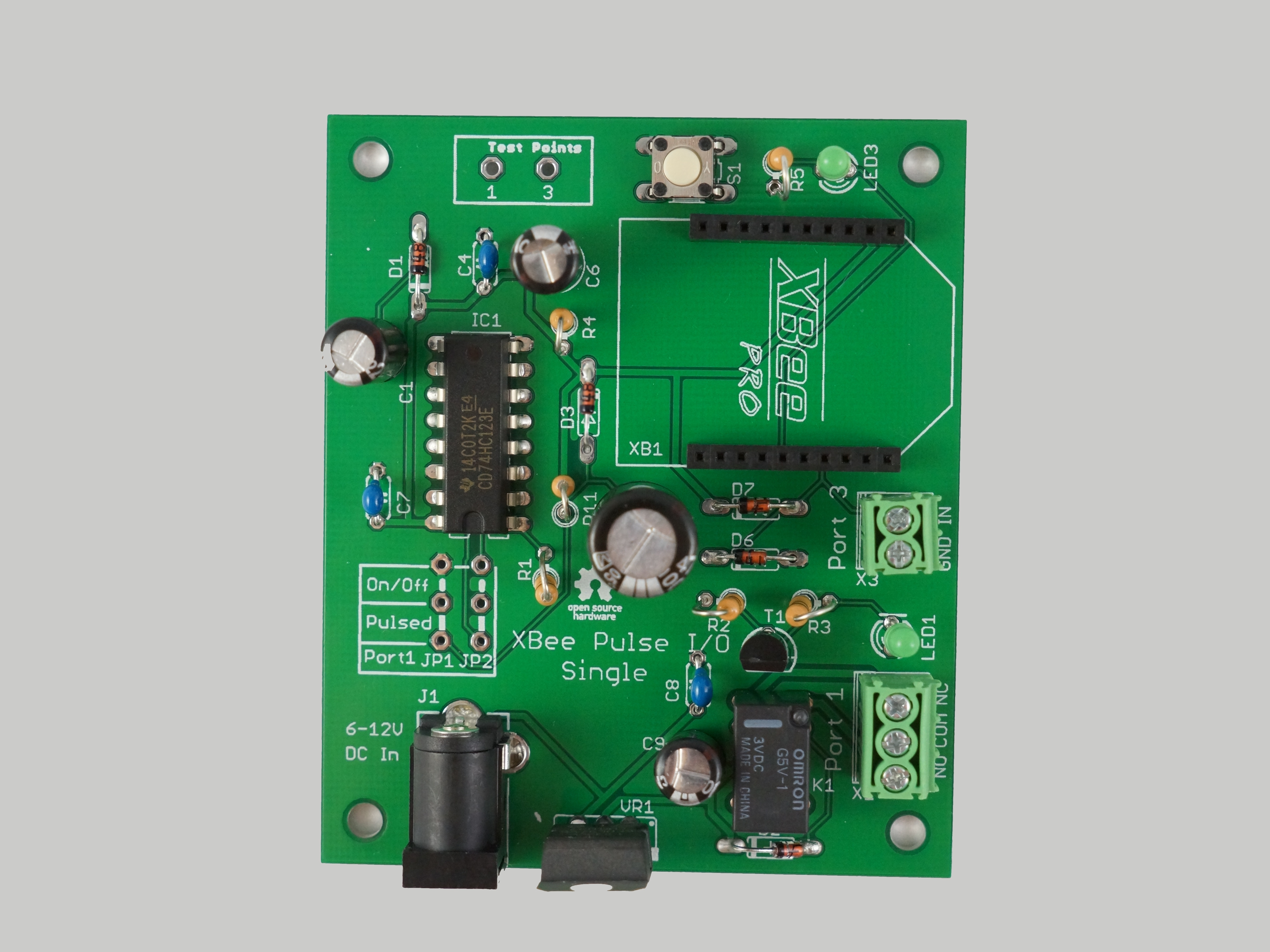
In this project we’re going to assemble the XBee Pulse I/O Printed Circuit Board — an open-source hardware design which can be used to automate things wirelessly. This hardware is used in the “12,000-mile Universal Remote” project from Make Vol. 30.
Projects from Make: Magazine
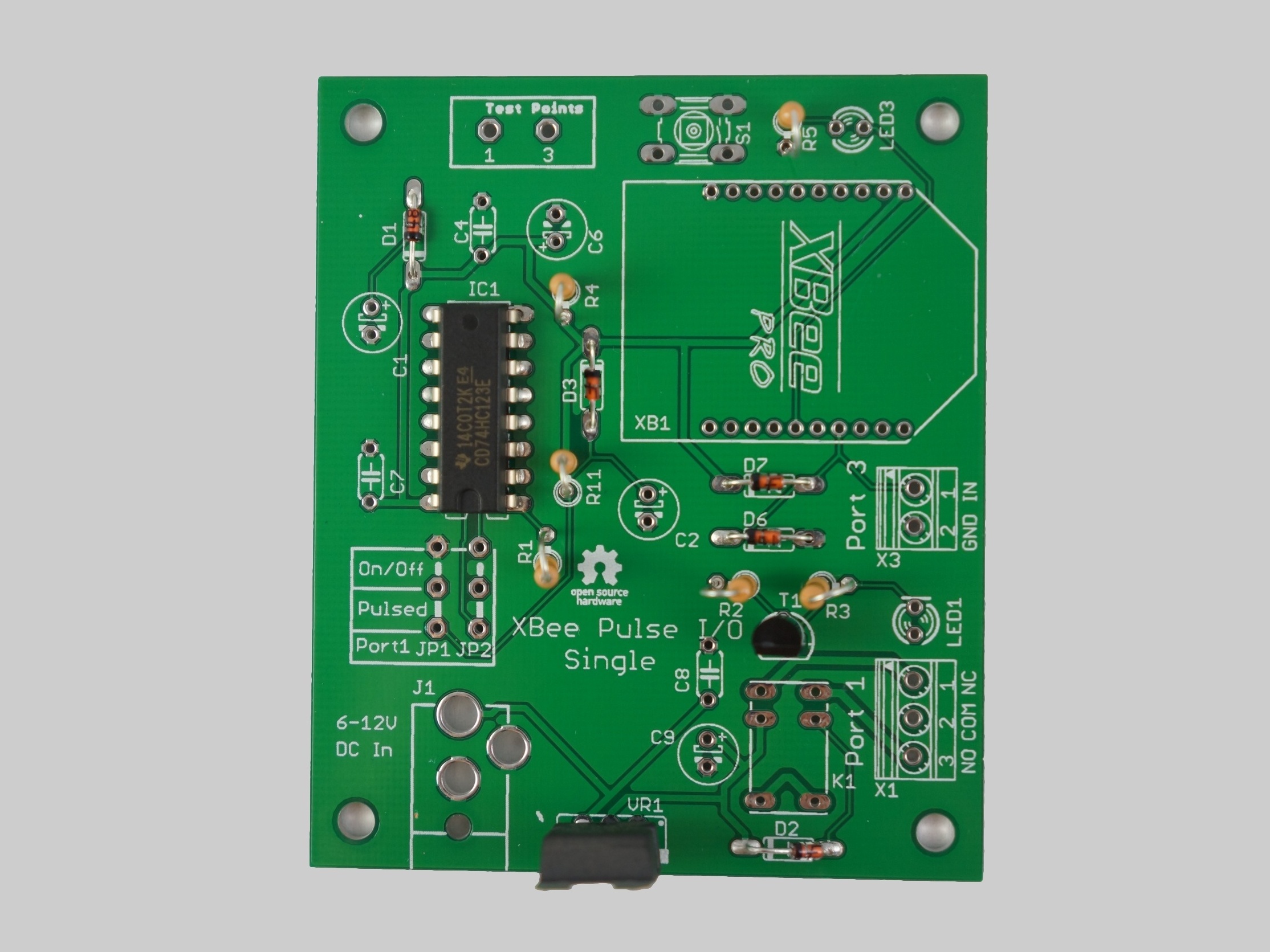
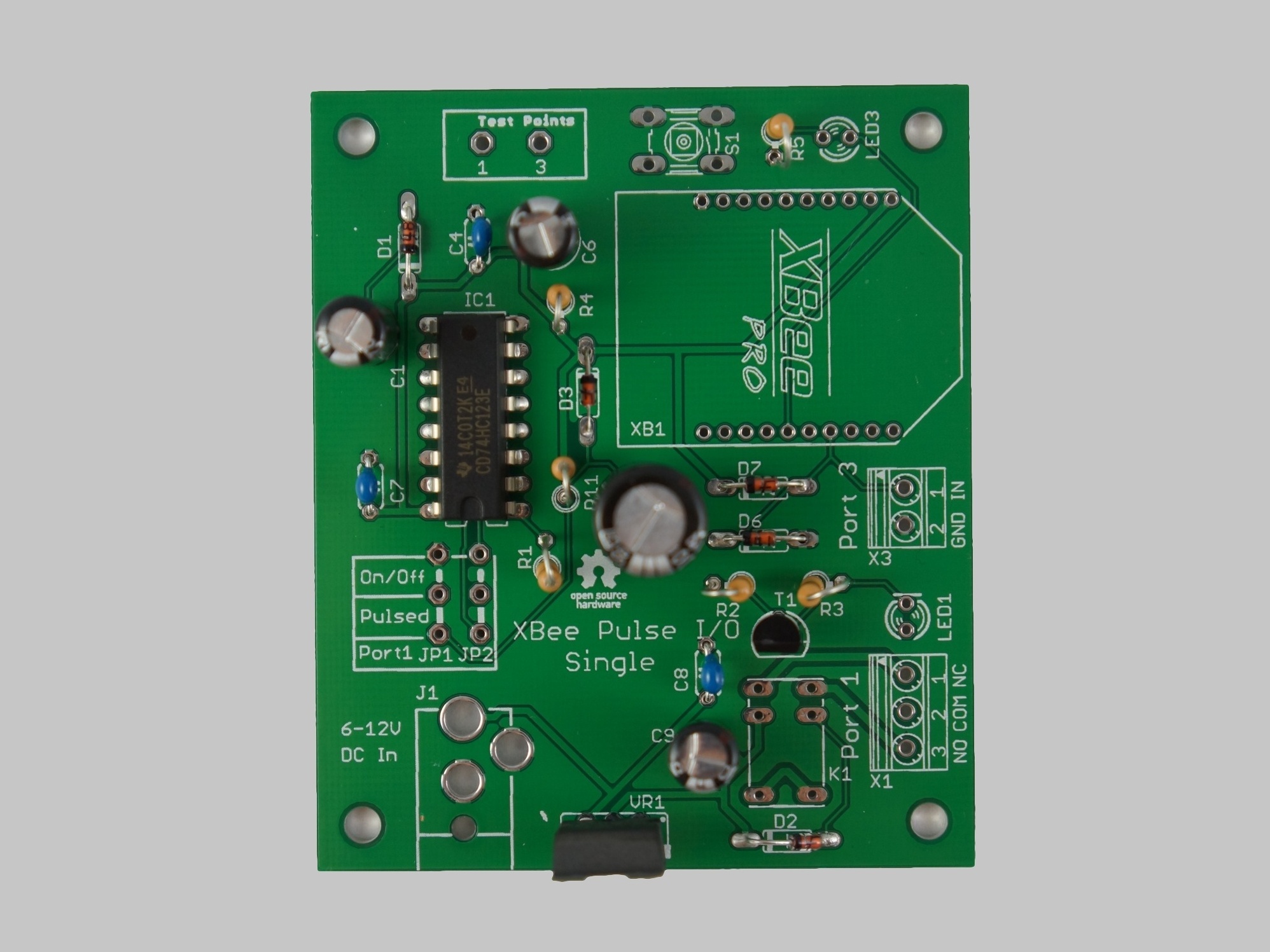
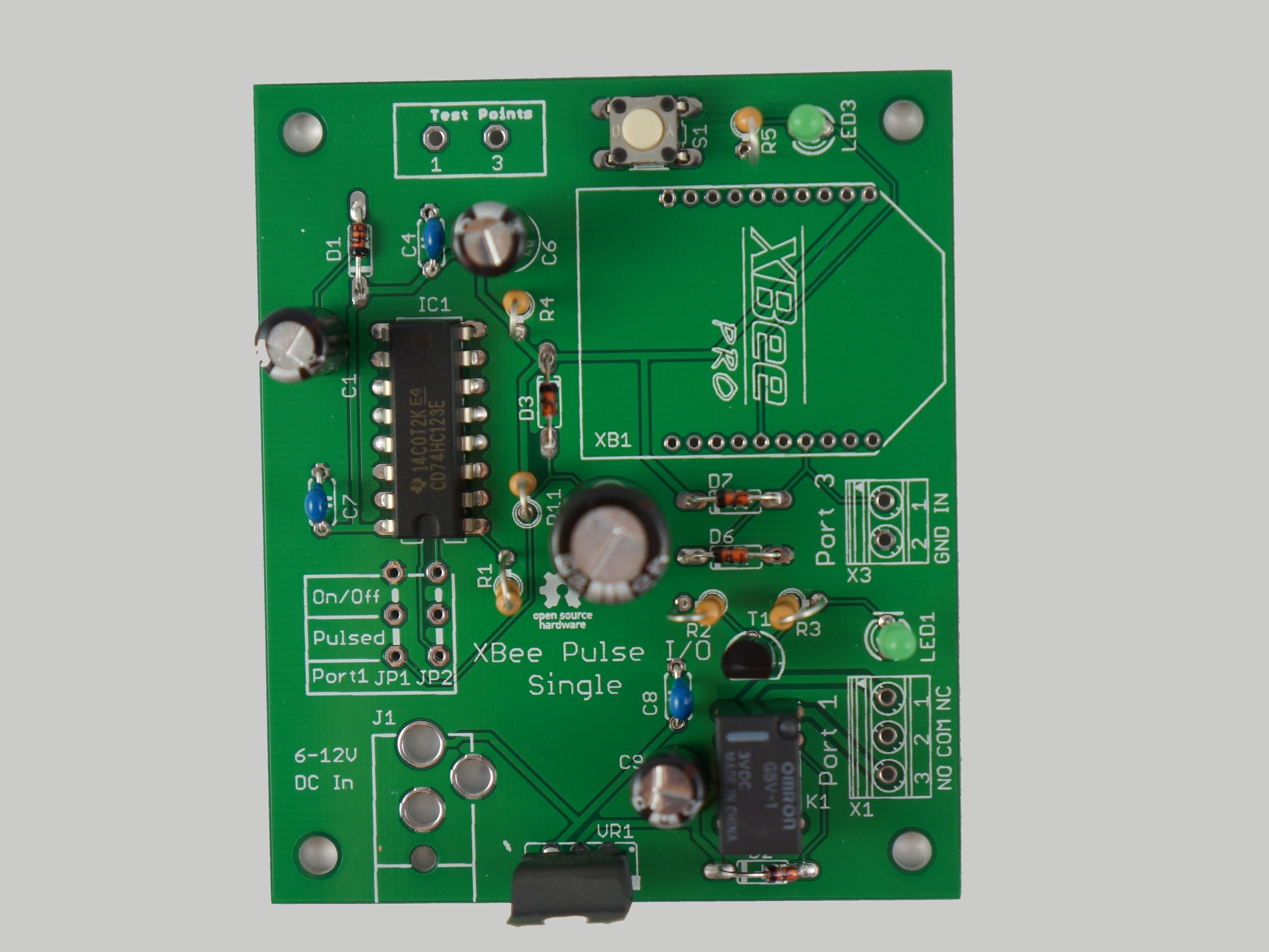
XBee Pulse I/O Single Port Assembly Instructions
This XBee kit is easy to assemble.