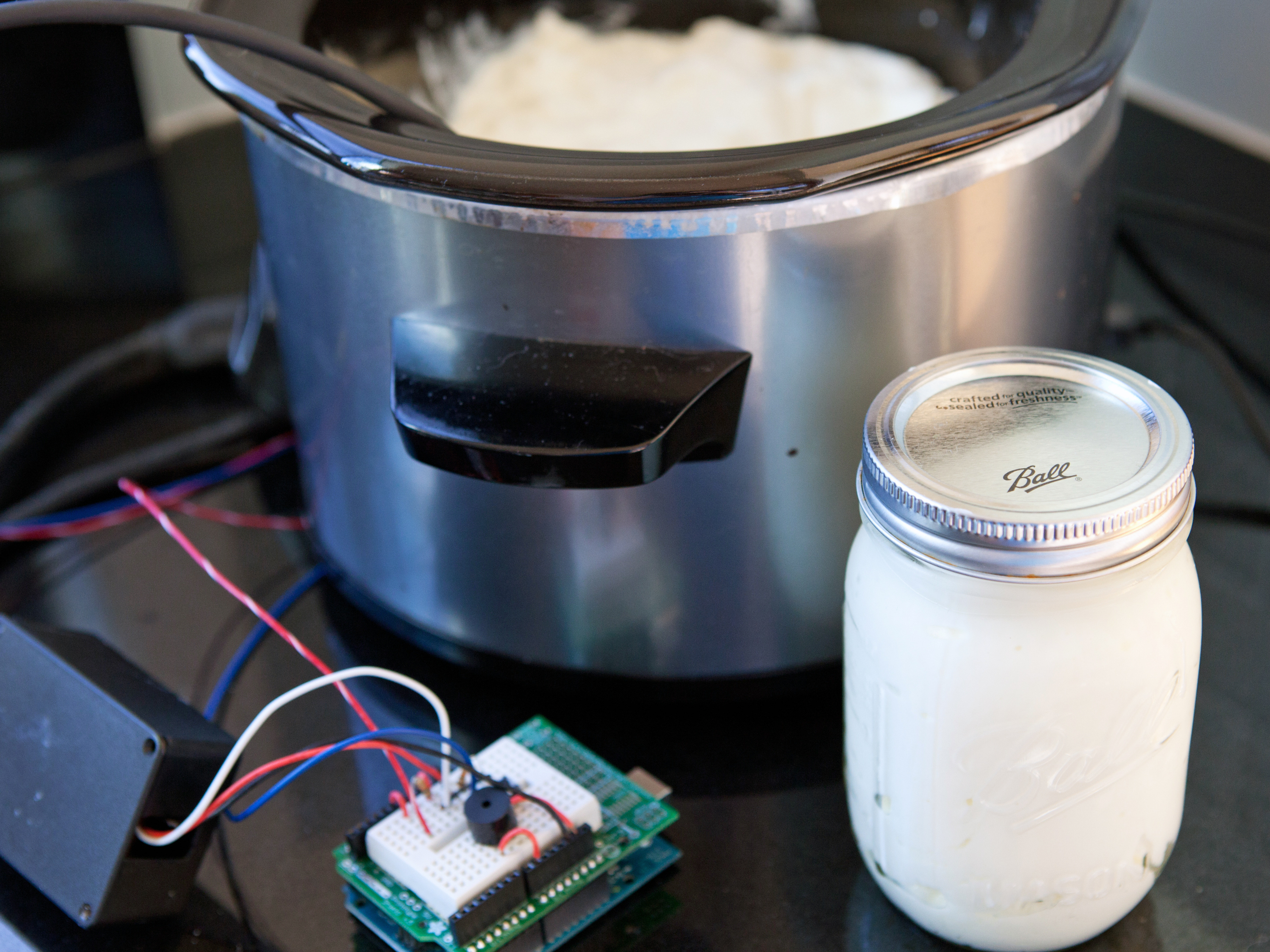
I’m lazy. My impatience often leads me to botch important steps when I make yogurt. So to get better control over the fermentation process, I made a crockpot thermostat attachment to precisely control the temperature.

You can buy electric yogurt makers, but most of them only incubate; the heating/sterilization step still has to be done on the stovetop. I wanted to experiment with Arduino microcontroller programming and electronic circuit design in Fritzing (an open source circuit layout tool that lets users document and share designs), so why not combine them into something I enjoy doing?

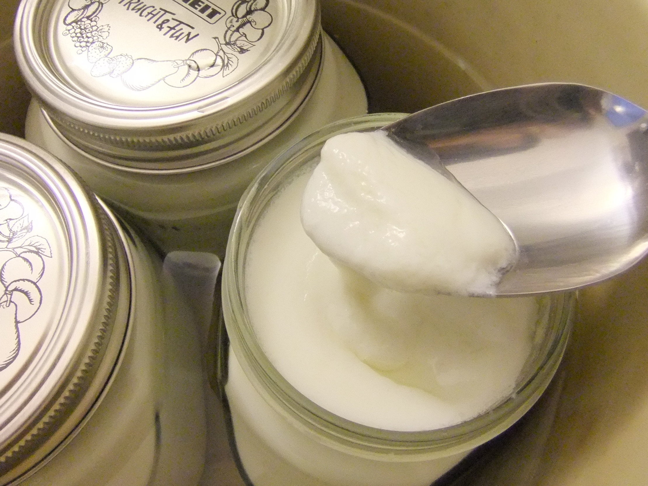
With my old-school yogurt recipe (adapted from wikihow.com/Make-Yogurt), I’d use a stovetop and a candy thermometer to heat the milk to 185°F and cool it to 110°F, then use a warm oven or radiator to ferment it at 100°F. That takes a lot of attention, and more containers than I care to wash later. Even with a commercial yogurt maker, I’d probably have to heat the milk myself, and that’s the step I’m most likely to botch.

Don’t get me wrong — it’s a great recipe as long as you’re diligent. But the combination of boring, time-consuming, temperature-sensitive steps puts my diligence to the test; that’s why the automation of an Arduino-controlled crockpot yogurt maker makes perfect sense to me.

Project Steps

How the Temperature Control Works

I plug my crockpot into a relay, which in turn is connected to the wall socket. I leave the crockpot switched on, so that the relay controls when power is supplied to the crockpot. The relay is toggled on and off by an Arduino microcontroller, based on readings from a waterproof temperature-sensitive resistor — called a thermistor — placed inside the crockpot. I put my yogurt containers in a water bath inside the crockpot to ensure even heating, then submerge the temperature sensor in the water.

A voltage divider circuit is used to indirectly measure the resistance of the thermistor. In the code that runs on the Arduino, I use the Steinhart-Hart thermistor equation to translate the thermistor’s resistance into temperature. This gives a pretty good idea of the temperature inside the crockpot. In addition to the thermistor’s resistance at a given time, the equation needs to be fed 3 coefficients, which can be calculated from predetermined thermistor resistances at different temperatures, shown on the manufacturer’s data sheet.

You can use a simple online calculator (makezine.com/go/thermistor) to get your coefficients for a given temperature range, or do the calculations yourself (makezine.com/go/diy_calc). Since we’ll be measuring a range between 100°F (38°C) and 185°F (85°C), I used resistance values measured at 86°F (30°C), 140°F (60°C), and 194°F (90°C) to calculate my coefficients. The code that decides whether the crockpot should be on or off is very simple; it checks the temperature once per second and turns the relay on or off if the temperature is under or over the target temperature.

If the temperature control were variable, like a dimmer switch, then it might make sense to use a more complex control called a proportional-integralderivative (PID) algorithm. PID controllers use a sophisticated set of rules to control things like heat or pressure and keep them from overshooting their target values (see “Sous Vide Cooker,”). For our purposes, though, a simple approach works fine.

Prepare the thermistor.

Since the temperature readings will be taken in the water bath, we need a way to keep the thermistor from getting wet. I found a great reference online for constructing a waterproof sensor (makezine.com/go/sensor1).

I waterproofed my thermistor by first soldering the thermistor onto 2 long (~3′) hookup wires, then wrapping the exposed wires with electrical tape.

I slid a short length of aluminum tubing over the sensor, then used moisture-resistant heat-shrink tubing and a heat-shrink end cap (on the open end of the tube) to seal both ends. You can use a heat gun or hair dryer to seal the tubing; you could also use epoxy to make the seals.

Construct the relay.

The Relay Control PCB from SparkFun comes disassembled, so you’ll solder the components to theboard: relay, 1K resistors (2), 10K resistor, diode, transistor, and LED. If you follow the component labels silkscreened onto the board, you shouldn’t have much trouble.

A few tips:

The relay will only fit in the correct orientation.

The line on the diode must match the line on the board.

The flat side of the transistor lines up with the flat side of the outline labeled 2N3904.

The unlabeled circular outline is for the LED. Face the flat side of your LED’s base toward the flat part of the outline. If your LED lacks a flat side, its shorter lead should face the flat outline.

SparkFun has a great tutorial for constructing a 120V relay outlet specifically for this relay board (sparkfun.com/tutorials/119). If you’re uncomfortable working with high-voltage control or just don’t feel like soldering as much, you can also check out SparkFun’s PowerSwitch Tail, a premade version of this relay at sparkfun.com/products/9842.

Here is the yogurt maker’s relay assembly. I deviated slightly from SparkFun’s instructions by using a female connector instead of a GFCI outlet. Use the extension cord’s male end with 12″–14″ of cord attached. Expose the cord’s 3 wires in the middle of its length, then cut the black wire and solder the ends to the relay board’s Load 1 and Load 2 connections. This is where the line voltage toggles on and off.

Attach the 3 wires at the end of the cord to the female connector: the green/blue wire (ground) to the green screw terminal, and the black and white wires to the other 2 terminals. Use a connectivity tester to make sure the larger slot receptacle is connected to the larger prong on the plug.

The solder points on the relay are basically live exposed wires, so use a project enclosure to keep the relay from accidentally being touched

CAUTION : Be extremely careful when working with line voltage, as it can actually kill

Build the circuit.

Assemble the circuit, following these images. The former was drawn in Fritzing (fritzing.org), an open source tool for creating interactive electronics. It offers a visual mode that lets you document circuits the way they look in real life — a great feature for those of us who aren’t electrical engineers or are just visual thinkers.

The best part is that the visual mode is linked to a schematic diagram drawn with traditional electronics symbols, which can really help newbies to see the translation between the visual layout (first image) and the schematic layout (second image).

Load the code.

Download the code from cdn.makezine.com/make/25/Chris_Reilly_yogurt_maker_arduino_code.txt and load it onto your Arduino.

The program controls 3 stages of temperature for making yogurt:

Stage 1: heats milk to 185°F for 10 minutes, to sterilize it and denature enzymes in it. (It’ll reach 185°F faster if you cover the pot with a towel or blanket.) When Stage 1 ends, the buzzer sounds for 1 minute.

Stage 2: cools the milk to 110°F. During this stage it’s useful to remove the cover and any insulation to allow for faster cooling. When the temperature reaches 110°F, the buzzer will signal. The temp will hold at 110°F for 10 minutes, then Stage 2 ends. That’s when you’ll add yogurt or starter culture and seal the containers.

Stage 3: incubates the yogurt at 100°F for 8 hours then shuts off the heating element. This period can be increased to taste; the longer the fermentation, the more sour the yogurt. At the end of Stage 3, the alarm will sound for 10 minutes, at which point the yogurt containers should be refrigerated.

Make automatic yogurt.

Wash everything! Before starting, gather up all the containers, lids, and stirring utensils to be used. Thoroughly wash them with very hot, soapy water. then rinse them all well with more hot water.

Then follow this recipe and let your Arduino do the cooking.

Ingredients

½ gallon of milk

1 package dry milk

Yogurt or starter culture

Step 1: Add the dry milk to the wet milk. Stir thoroughly.

Step 2: Fill the containers and place in a water bath in the crockpot.

Step 3: Loosely cover the jars to prevent condensation from dripping in, and insert the thermistor in the water bath.

Step 4: Plug the crockpot into the relay, and the relay into a power source.

Step 5: You can insulate the crockpot by covering it with towels or blankets to help the heating stage go faster. The milk will heat to 185°F.

Step 6: Plug the Arduino into a computer. The serial monitor will give feedback and instructions.

Step 7: After the milk has cooled to 110°F, add about 1 tablespoon of starter or yogurt per container.

Step 8: Seal the lids tightly and incubate for 7 hours (or more) at 100°F. It’s yogurt! Refrigerate after opening.

Conclusion

This project first appeared in MAKE Volume 25.