Photo by Matt Alavi

When things break around the house it usually means a trip to the hardware store for replacement parts, but when my doorbell chime stopped working, I saw it as an opportunity to use some animatronics skills and make something more fun and aesthetically pleasing than a standard “ding-dong” type doorbell. This is how ZenBot was born.

YouTube player
This article appeared in Make: Vol 81. Subscribe today for more projects.

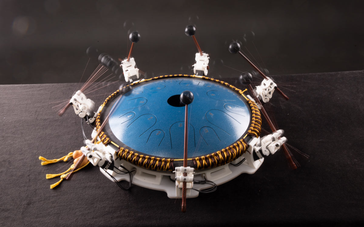
ZenBot is an Arduino device that, by means of seven mallet-wielding 2-axis mini robots, can play soothing percussive tones on a meditation drum, aka tongue drum. While ZenBot was meant to be a basic doorbell, it has potential to be expanded into a MIDI instrument by using available open-source libraries, or even downsized to work with a smaller drum in order to significantly reduce material costs.

In this article I’ll cover my design process while also providing enough explanation and online resources for you to build one of your own. Along the way you’ll learn about design organization, setup and use of Dynamixel robotic servos, and beginner-level Arduino programming. Before we jump in, check out the video of ZenBot playing Tears for Fears’ “Mad World” below. You’re going to want to build this.

YouTube player

Design Guidelines

As a starting point, I set a few guidelines and limitations for myself in order to narrow down
the options:

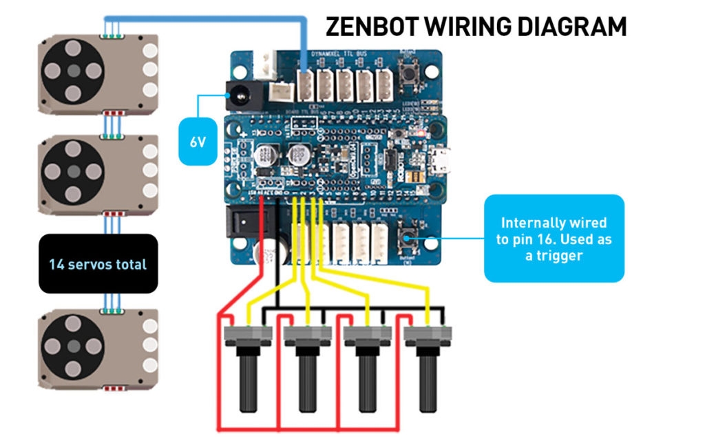
  • Utilize Robotis XL330-M288-T servos for their low cost and programmability — and because I already owned a box of 25 of them that were longing to be used.
  • Utilize a specific 14″ tongue drum which I had also recently purchased.
    All parts must be printable on my Ultimaker 2 Extended 3D printer. (All but one ended up being done this way.)
  • Design must be modern looking yet work well with the more traditional feel of the drum itself.
  • Design must be axially symmetrical in nature.
  • Design must mimic human hand motion using rubber mallets. For a while I considered using solenoids, but swinging mallets just felt like a more fun and organic approach.

Building Your Own

YouTube player

To build your own ZenBot, download the Fusion 360 files for printing and the Arduino code for the microcontroller, and watch my video tutorials that will take you through the build in fine detail.

Take care to measure your components well. Drums and mallets that are handmade are not always built to exact measurements. If yours are a bit different than mine, you might need to make minor adjustments to the robot parts. This is where the Fusion 360 files will come in handy.

Taking It Further

Now that you have the skills to build your very own ZenBot, here are some ideas for taking it to the next level:

  • Convert the code to accept live input from a MIDI keyboard, or maybe turn it into a modern MIDI-controlled player piano-type instrument.
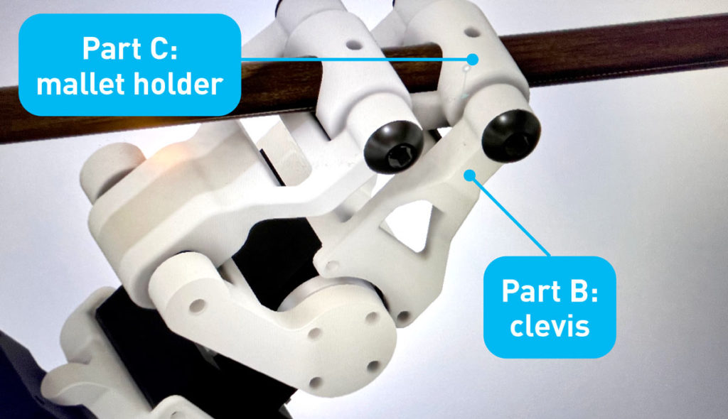
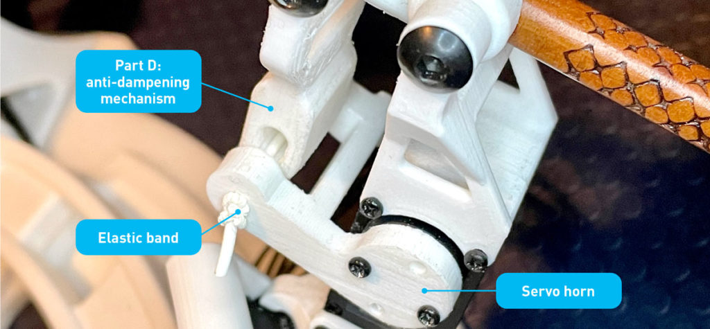
  • Experiment with the anti-dampening mechanism or create your own version. Maybe try a flexible/compliant mechanism instead of the elastic band to make it more durable and use fewer purchased parts.
  • Make the trigger button wireless. Maybe use Bluetooth or RF to trigger the drum from a distance.
  • Design a smaller, low-cost version by using a smaller drum with fewer tongues. Reduce the servo count from 14 to 7 by eliminating the need to rotate.
  • Or take what you learned here and apply it to a xylophone, tubular bells, chimes, or any other melodic or percussive instrument.

No matter what you do with it, one thing is for sure, you will have a beautiful functional art piece that is sure to be a great conversation starter!

This article appeared in Make: Volume 81.

Project Steps

Rotation Mechanism

With 14 notes on the tongue drum, I decided to build 7 identical robots, each able to hit a note on the larger tongue and then pivot to the smaller tongue to hit the same note an octave higher.

Dynamixels are great for their modularity. Designing a rotation move was as simple as creating a bracket, Part A, that could be bolted onto the servo horn of the base servo and also onto the body of the second servo.

On a design with stronger forces acting on the joint, this approach would’ve been inadequate, but in this scenario, the simple approach was sufficient.

Strike Mechanism

Designing the strike mechanism was a little more involved. It required deciding what paths I wanted the mallet to travel within. After determining this, I was able to pick the axis of rotation for the pivot, as well as the second axis that the stick would rotate around as it swung up and down. Once I had the pivot positions figured out, I designed a lightweight structure that supported the clevis joint, Part B, as well as the mallet holder, Part C.

Anti-Dampening Mechanism

I was afraid that if the servo couldn’t change directions fast enough after hitting the drum, it would result in a muted and not very pleasant-sounding tone. The mallet needed to strike the drum hard but also retract fast enough to allow the tongue to resonate. I solved this in the simplest way that popped into my head: Part D. The mallet would be pushed by a stretched rubber band. The band would stretch a bit on the way down, then release the force onto the mallet like a slingshot. The servo would already be retracting as the mallet hit, then the rubber band would catch the mallet on the way up, thereby keeping it from dampening the sound or double bouncing on the drum.

But this method would require finding that perfect synchronization between the elastic, the mallet, and the servo position in order to work. I wrote an Arduino sketch that allowed me to use potentiometers to dial in the position when the mallet is down, position when the mallet is up, and the amount of time in millis() (milliseconds) between when the down command and the up command are sent. Once I had the numbers needed to get the loudest and cleanest sounding note, I just plugged them into a function that handles the mallet strike of each robot.

Support Structure

After part cleaning, thread tapping, and assembly, I had a complete mallet assembly which, after a successful test, was duplicated 6 more times to cover the rest of the notes on the drum.

The next step was a solid surface to mount them onto. The base, Part E, was designed to not only hold the servo, but to also help capture the edge of the drum to keep it held down in the center of the circle. Care was given to allow clearance for screwdrivers and screws to reach their mark as well as the servo cables that needed an exit path.

At this point, I still had 7 individual robots with nothing keeping them grounded at the proper location relative to the drum. I designed some bridge parts, Part F, to help fix the robots in their proper place and orientation.

Now the servos were bolted together into a single assembly, but it needed a little more support, so a piece of acrylic was laser cut to become the foundation, Part G, that everything was then bolted onto.

I could have designed it as 7 pieces that could be grown on a 3D printer, but because I had a laser cutter available, the simplest solution was to laser cut a single part and bolt everything onto it.

Wiring the Circuit

Electronics Overview

Wiring these Dynamixel servos is very easy since they can be daisy-chained together. It’s important to note that they are all factory assigned ID number 1. So I used the U2D2 programmer and Dynamixel Wizard app to assign each servo a unique ID number. I chose to label the rotation servos with ID’s 1–7 and the corresponding mallet strike servos as 11–17.

At this point I simply created a chain going from 1 to 11, 11 to 2, 2 to 12, and so on. The last servo got a longer extension and plugged into the Arduino-based OpenCM 9.04 microcontroller with expansion board. The expansion board allows for other types of Robotis servos to be used and has a nice power switch and DC input plug.

For this device I simply added a pushbutton switch to represent the doorbell trigger. It is possible to incorporate a wireless switch to trigger the sequence, but for me a wired switch was able to do the job just fine.

Programming

Code Overview

I figured out early on that the drum when hit by the mallet will just ring on, so the start of the note matters here, but its end is not controlled. This means that a 16th note and a quarter note will sound the same. This eliminated the need of complicated code to handle timing.

The general idea was to create seven arrays, one for each robot. Within the array, each piece of data represented one step in time, and the value determined what the robot would do. A value of 0 doesn’t play any notes, while a 1 will play the low note, and a 2 will play the octave note on the smaller tongue.

If the start button was pressed, the robot will play a low note, high note, or rest, as per the first data value in each array. It will then look ahead and reposition itself based on the next note that needs to be played.

When it is time, the next note will play, and the process will continue until all the notes in the array are played. The tempo is governed by a simple delay executed after each note packet is executed.

This approach works great if you are creating a “set it and forget it” type of device, such as a doorbell. Filling the arrays with notes can be a little time consuming, but once it’s populated, you’re done. For any other application, perhaps turning it into a MIDI instrument might be more beneficial.