Can you be electrocuted in the bathtub? Sure — but only because the water’s not pure. Many people don’t realize that absolutely pure water doesn’t conduct electricity. This is because the hydrogen and oxygen atoms don’t have free electrons. In a typical domestic water supply, it’s the impurities such as sodium, calcium, and magnesium salts that enable electrons to flow.
This interesting fact means that you can assess the purity of water by measuring its electrical resistance. The higher the resistance, the purer the water should be (although this test won’t reveal contamination by substances such as organic compounds).
The simple circuit in this project can test water samples without any need for a multimeter.
The basic concept is to use a small volume of water in a voltage divider. You can then compare the output from the divider with a reference voltage, and amplify the difference. When the output is passed along to a timer chip, you’ll hear a sound that changes with the purity of the water.
The concept of a voltage divider is illustrated above. When an input voltage, shown as Vin, is applied across two resistors in series, you can calculate the output voltage, Vout, at the point between the resistors. If both the resistors are the same value, Vout is half of Vin. If R1 is twice the value of R2, Vout is one-third of Vin. And so on. (If you add a significant load to the output, Vout will be reduced.)
If you use a water sample instead of R1, Vout will vary with the purity of the sample. You can then compare it with a constant reference voltage, shown as Vref, created by a second voltage divider .
Because the difference between Vout and Vref may be small, you need to amplify it. This is easily done with an operational amplifier, commonly known as an op-amp, such as the venerable LM741. The symbol for an op-amp is shown below, although when you see it in schematics, you’ll find that people often don’t bother to show the power supply.
The plus and minus symbols inside the triangle identify the “noninverting” and “inverting” inputs, respectively. The output from the op-amp increases when the noninverting input increases, or decreases when the inverting input increases.
The image above shows the op-amp in a circuit using the water sample and the reference voltage as inputs. I substituted a potentiometer for one of the resistors, so that you can control the amplifying power with negative feedback to the inverting input. (There are many other ways to wire an op-amp, which you can easily find online.) Pin functions of an LM741 chip are shown below .
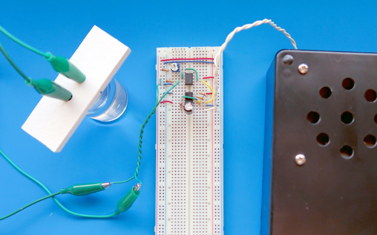
I connected the output of the LM741 to a 555 timer, using pin 5 of the timer to control its audible frequency. In the schematic below, the complete circuit is laid out as you might wire it on a breadboard.
You can find a lot more information about timer chips in my book Make: Electronics.
Commercial resistive water testing devices use platinum contacts, but that was a bit beyond my budget, so I used a pair of pennies. Try to find some that are as new and bright as possible.
To mount the pennies, you can use a piece of plastic or plywood about 1″× 3″ and ¼” thick. Drill a couple of holes ¼” in diameter, about ¾” apart, and make saw cuts across them, as shown below.
Poke your alligator clips through the holes to grab the pennies, and pull the pennies into the saw cuts to maintain them at a fixed distance apart. The assembly is shown below. The other ends of the patch cords will grip jumper wires that plug into your circuit.
You can rest the penny assembly across any small cup that is filled almost to the brim with liquid. I used some little plastic containers like the one shown below.
Prepare some samples consisting of distilled water, municipal water from your faucet, and bottled spring water (which often contains minerals). You can also try dissolving table salt in water. Label your samples so you don’t get them mixed up.
After you note the result using one liquid, remove the pennies, wipe them with a tissue, and try the next liquid. When the sound you hear is higher-pitched, this means that the resistance is higher and the water is purer.
You can also experiment with other kinds of liquids. I tried mouthwash, milk, and sports drinks (which have a lot of minerals added).
Two factors may make it difficult for you to get consistent results. First, carbon dioxide in the atmosphere quickly dissolves in water, forming carbonic acid. This disassociates to form ions that lower the resistance of your sample. So, keep your container of distilled water sealed, and when you pour some into a cup, test it as quickly as possible.
Second, when you pass DC current between electrodes immersed in a liquid, positive ions gather around the negative electrode while negative ions gather around the positive electrode. This inhibits electric current, so that the resistance seems to increase, and you’ll hear the sound from your circuit gradually rising in pitch. You can minimize this effect by agitating the liquid. Commercial equipment deals with this problem by using AC instead of DC, while running liquid past the electrodes in a steady flow.
Even though you can’t expect precision results, you should be able to show that tap water conducts electricity better than distilled water. And if anyone doubts this — just ask them to listen to the difference.
Our websites use cookies to improve your browsing experience. Some of these are essential for the basic functionalities of our websites. In addition, we use third-party cookies to help us analyze and understand usage. These will be stored in your browser only with your consent and you have the option to opt-out. Your choice here will be recorded for all Make.co Websites.
Allow Non-Necessary Cookies
Escape to an island of imagination + innovation as Maker Faire Bay Area returns for its 15th iteration!
Buy Tickets today! SAVE 15% and lock-in your preferred date(s).