IMG_3004 Photos: Christopher Alden

In building our latest project, The Great Houdini Escape Room, located in the Palace of Fine Arts in San Francisco, we tackled many Maker challenges. Everything in the room was built from “scratch.” The room uses over 5,000 feet of wire and is operated on over 5,000 lines of code running on 8 Arduino Megas. Those Megas connect to hundreds of inputs and outputs, including nearly 50 objects (such as lights) that are high voltage or, at least, require more voltage than the 5V that an Arduino can pump out.

Low voltage and high voltage environments are very different, and it can be challenging to build a complex system that requires both environments to work together seamlessly. And, of course, low-voltage systems are safe (think batteries) while high-voltage systems are dangerous (think wall sockets).

Since current can’t flow directly between low- and high-voltage networks, the interaction between these two systems is often managed via a relay. Data from an Arduino triggers a relay, which in turn switches a high-voltage connection on or off. Think of it as a light switch.

Wiring a relay, however, can be tricky. One side is low voltage and the other high. There needs to be a safe area for these relays to operate, away from tinkering hands. Arduino is fun because wires can be plugged in and moved at will — all without risk of electrocution. But once you bring high voltage into the mix, that easy plug-and-play ability goes away.

Wiring a relay is not a major undertaking, but we had to wire 50 of them. More significantly, however, we wanted to have the same flexibility with our higher-voltage elements as with our Arduino powered elements — it should be just as easy to swap out a lightbulb connection as an LED.

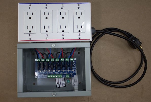
So we created the Plug & Play Arduino Relay. In brief, we put the relays in a junction box and mounted an electrical box on top with regular wall outlets inside. By wiring these outlets to the relays we created a plug-and-play device that works on both ends. Data wires come out of the box and can be safely connected to an Arduino. And any electrical device with a plug on the end — be it a light, a fan, or a blender — can be plugged and unplugged, as easily as you would with a simple power strip.

We built several of these reusable devices — there are eight used in the Great Houdini Escape Room — and now, any time we need to add, change, or remove a high-voltage device, there is no tricky high-voltage wiring needed – just plug and play.

IMG_2580

WARNING:

This project involves wiring for high-voltage applications. Use caution whenever dealing with high-voltage wiring, including following directions carefully and general safety practices. Safe assembly and operation of this project is the user’s responsibility. Do not make changes to the system while the device is plugged in.


Editor’s note: Alden’s Great Houdini Escape Room was profiled recently by Make: See our coverage here. Alden is interested in hearing more ideas for how he can improve on the design, either of the relay or upcoming escape rooms themselves. Visit him on the web at palace-games.com.

Project Steps

Prep Electrical Boxes

Remove 4 knockouts from the 4-gang electrical box.

Place electrical box on top of junction box and mark knockout holes with a marker.

Drill holes in junction box for ½” connectors. (A step bit works great for this.)

Build Box

Attach electrical box to junction box with box spacing connectors and nipples. (Keep the spacers toward the outside.)

Attach wood 2×4 block to back of outlet box with 2 screws. This will make the boxes more stable.

Prep for Relay Board

Drill out relay board hole to 9/64″ so they accommodate 6-32 screws to pass through.

Place relay board in the center of the junction box and mark the 4 corners with marker. Drill 5/32″ holes at each mark.

Place Spacers

Make or buy 1.5-2″ plastic spacers. (We 3D printed some and tapped them to size 6-32.) Install inside of junction box.

Ground It and Install Power

Install a ground wire to connect both boxes together, leaving extra length in outlet box.

Install cord with cord connector and male cord end. Match up wire orientation with plug configuration; only one end of cord is correct. Black wire to darker screw, white wire to silver screw, green wire to green screw.

Prep Outlets

Break off the tab connecting the darker terminal screws on all of the outlets.

Cut 4 blue and 4 red wires 10″ in length and crimp a fork terminal on one end. Attach blue wire to the top dark outlet screw and red to the bottom screw.

Cut 3 white wires 3.5″ in length and strip ends, and connect to silver screws on outlets.

Connect Outlets

Connect all the grounds together and connect the neutral cord wire (white) to the outlets.

Feed the red and blue wires from each outlet into the junction box through the connector that lines up with said outlet.

Cut 2 black wires 10″ in length and 6 wires 2″. Wire nut 2 long wires to the black cord wire and feed into the junction box.

Install Outlets and Cover Plate

Mark the top of the plate with a blue marker and the bottom with red. By doing this and running each outlet wires directly below it, it is clear to see which wire controls which receptacle.

Connect Relay

Connect the two long black wires to the high-voltage terminal blocks on the relay. Use the short black wires to make sure one terminal of each block has power.

Connect the blue and red wires to the open terminal on each block. The relays are numbered 1–8, so you can easily write the corresponding number on the outlet or plate.

Mount Relay Board

Fasten relay board to plastic stand-offs with ½” 6-32 screws and push any extra wire up into the outlet box.

Remove a knockout in the junction box and insert a protective bushing. Your low-voltage control wires can be routed through here. An added cable clamp can provide strain relief, or there are a variety of connectors one could use to have the low voltage “pass through” the box.

Wire Arduino Connectors

Cut a length of Cat-5 cable long enough to reach from your Arduino to the P&P Box.

Cut an equal length of red and white bell wire or two lengths of hook up wire, one red and the other black (20–22 gauge).

Strip the outer shell on both sides by 3″. Strip each of the 8 wires within by 1/4″. Strip the ends of the bell/hook up wires by 1/4″.

Screw the 8 wires into the 8 green terminal blocks at the bottom left of the relay. Come up with a consistent pattern so that you will know which color wire connects to which color relay. Our pattern is: blue/white, blue, orange/white, orange, green/white, green, brown/white, brown.

Screw the bell/hook up wire to the ground (GND) and power (VCC) green terminal block on the bottom right side.

Connect to Arduino

Run the Cat-5 and the other two wires out of the junction box, through the protective bushing. Use electrical tape to bound them together.

Connect the other end of the wires to the terminal block. We use a terminal block because Cat-5 is too thin to fit well in Arduino pin sockets. We also find that this allows for useful modularization. Make sure to connect them in the same color order that you used on the relay. Connect the other two wires to the remaining two spots in the terminal block.

Use hookup wire to connect the Arduino power to terminal block for the red wire and ground to the white or black wire.

Use hookup wire to connect any Arduino pin of your choice to any slot on the terminal block, depending on which outlet you want to control with which pin.

Plug and Play

Your Arduino can now control high-voltage power outlets. To demonstrate its abilities, try the sample code below. It will test the setup, turning the relays on and off one at a time.

Download the code here: cdn.makezine.com/make/MAKER_8_Relay_Sketch.ino