This article appeared in Make: Vol. 88. Subscribe to Make: for more great articles.

Hardware builds are seldom described as “touchable,” “cuddly,” or “cute,” but I’ve found that embedding programmable electronics in soft accessories like handbags (“Bag to the Future,” Make: Volume 87) and pillows (“Pixelblaze Pillows,” Volume 83) produces projects with surprising tactile and visual appeal. Inspired by some clever and creative robot builders, I’ve experimented with placing controllers and peripherals inside plush sewing patterns to create soft, interactive companion bots. The results have been irresistibly cute and undeniably cuddly.

Make: has interviewed several talented makers whose companion robot builds started me down this path, and whose palpable enthusiasm provided the incentive to follow in their footsteps. Creator Jorvon Moss has designed an entire collection of clever robots with engaging personalities. Video host and hardware maker Alex Glow built an owl named Archimedes that sits on her shoulder and uses AI to respond to facial expressions. And maker/educator Angela Sheehan presented her adorable color-changing plush dragon, Nova, at the recent Hackaday SuperCon conference. Nova’s lifelike movements and appealing softness were direct inspirations for my projects.

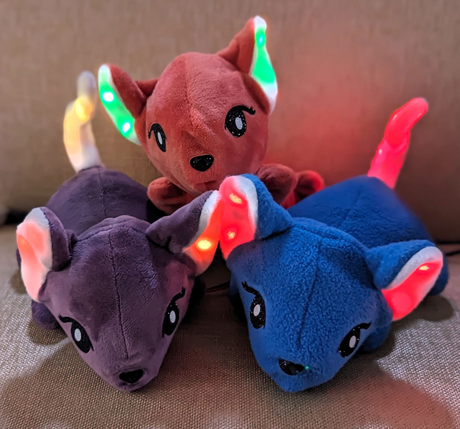
This article’s featured bot, Rosie the Radiant Rodent, is a good way to learn about making a mechanized soft companion. She packs a plethora of functionality into a deceptively small package. A 9g servomotor powers Rosie’s lifelike head motions, and three short “pebble” LED strings display colorful animations in her ears and tail. The two capacitive touch sensors inside Rosie’s paw and head detect even slight contact through her fabric shell, while a Useful Sensors “Person Sensor” makes simple work of detecting faces in her field of view.

Rosie’s responsive personality results from CircuitPython code running on an Adafruit Feather RP2040 controller, allowing her to respond to input by wiggling her head and changing LED animations. She even reacts to nearby admirers by lighting up whichever ear is on the same side as the closest detected face.

What will the next generation of Make: look like? We’re inviting you to shape the future by investing in Make:. By becoming an investor, you help decide what’s next. The future of Make: is in your hands. Learn More.

Project Steps

1. Read the rat plush pattern

The sewing tutorial and pattern for a rat plush animal are at available here. Download the PDF and read all instructions from beginning to end before proceeding.

The pattern instructions are clearly numbered, with lettered sub-sections. This tutorial does not reproduce the existing sewing directions but notes the steps where you should modify or deviate from the original instructions.

HINT: If you’re unfamiliar with sewing stretchy materials or navigating a sewing machine around tight curves, you should first sew the pattern as written to familiarize yourself with the required techniques.

2. Cut pattern and attach facial features

Print and cut the pattern pieces from fleece or minky fabric as directed by the sewing pattern instructions. Use saturated color plush fabric for the body, and white or cream fabric for the tail and inner ear. Select the ear pattern piece without the bite mark.

Figure A. Photo by Debra Ansell

In addition to the original pattern pieces, cut a second body bottom piece (pattern piece F) from thin quilting cotton (Figure A). Any color of cotton is fine, as this additional piece will not be visible.

Figure B. Photo by Debra Ansell

Pattern instructions 1 and 2 describe fusible web applique to attach fabric facial features. Depending upon the adhesive strength of your fusible web, these pieces may need reinforcement stitching around the perimeters. In my builds, I chose to make Rosie’s features from glitter heat-transfer vinyl instead of fabric, importing the eye and nose outlines from the PDF pattern into my vinyl cutter software (Figure B). You can use either method; a vinyl cutter can cut both fabric and heat transfer vinyl precisely, but if you have a steady hand, you can hand trace and cut the features with sharp scissors before ironing them in place.

Figure C. Photo by Debra Ansell

After the facial features have been ironed on and stitched if necessary, use the 5mm punch to create a hole directly in the center of the nose (Figure C) to create an opening for the Person Sensor module’s camera. Then complete sewing pattern instruction 3 as directed.

3. Sew the head and ears

Pattern instructions 4–8 describe sewing the ears and head. We will modify these instructions to create channels connecting the head and ear interiors, leaving a pathway for wires and LED strings to be added later.

Figure D. Photo by Debra Ansell

Follow instruction 4a as written. In instruction 4b, when basting the ears to the head front, do not sew all the way across the ear bottoms. Instead, baste just the portion where the ear is folded over on itself, as seen in the blue dotted lines in Figure D.

Figure E. Photo by Debra Ansell

Similarly, in instructions 4d and 5, baste the ears to the head front by sewing only the folded portion of the ears. Then separate the front and back sides in the unsewn ear half and baste just the light-colored ear fabric to the front of the face (Figure E).

Figure F. Photo by Debra Ansell

Next, follow pattern instructions 6a–6c as written to sew the head back pieces together, being sure to leave an opening as directed. Complete 7a as written. In instruction 7b, when sewing the head front and back together, stitch over the folded ear portions, but leave gaps where the open portions of the ears sit, as shown by the blue dashed lines in Figure F. Remove the assembled head from the sewing machine, then hand-stitch the dark ear fabric to the head back at the gaps in the machine stitching.

Once the head is assembled, with open channels from the head interior to the inside of each ear, invert the head as shown in instruction 7c. Skip instruction 8 and do not stuff the head at this point. Set the head aside until the body is complete.

4. Sew the back and tail

Follow pattern instructions 9a–9c and 10a–10b to sew and turn the tail. Skip instruction 10c and do not stuff the tail.

Next, we will modify instruction 11 to leave an opening at the base of the tail to insert an LED string. Begin instruction 11a by marking the body back pieces with tail placement lines. But instead of stitching through both layers of the tail, we will stitch each half of the tail base to a different body back piece, as shown in Figures G and H. It is easier to baste the small tail pieces by hand than by machine.

After basting the tail to both pieces which form Rosie’s back, align and pin the two back fabric pieces together with right sides facing each other and the tail sandwiched between them. Sew along the line depicted in sewing instruction 11cskipping over the tail opening.

Once the body back and tail pieces are all sewn together, verify that you can still access the tail interior through the opening, then set the assembled body back aside.

5. Insert the zipper

Now we’ll deviate from the pattern instructions to insert a zipper into the bottom fabric piece, to provide access to the finished bot’s interior.

Figure I. Photo by Debra Ansell

Using a Sharpie or fabric pen, draw the blue and orange lines shown in Figure I directly onto the wrong side of the quilting cotton piece. The long orange line should be centered inside the ½”-wide blue box, and the diagonal lines should branch off at 45° angles. The short ends of the box sit about ¾” from the nearest fabric edges.

Figure J. Photo by Debra Ansell

Next, sandwich the quilting cotton and plush body bottom pieces with right sides together and pin or clip around the exterior edges to hold them in place. Take both body bottom pieces and place them in the sewing machine with the quilting cotton on top. Referencing Figure I, sew completely along the blue lines forming the box. Remove the fabric from the machine and take out the pins. With fabric or embroidery scissors, cut through both layers of fabric along the orange lines, being very careful to stop just short of the stitches which form the box (Figure J).

Figure K. Photo by Debra Ansell

Push the quilting cotton through the newly cut opening so that the connected pieces now have their wrong sides together, then smooth the quilting cotton so it lines up with the plush fabric (Figure K). Gently iron the seams of the rectangular opening to flatten them.

Center the nylon coil zipper behind the opening, with the zipper front visible from the plush fabric side, then pin the zipper in place (Figure L). Be sure that the zipper pull is inside the opening. Attach a zipper foot to your sewing machine and carefully sew around the entire rectangular opening, staying close to but just outside the seam, removing the pins as you go (Figure M). After sewing the zipper perimeter, trim any zipper ends that overhang the fabric.

6. Sew body and attach the head

Figure N. Photo by Debra Ansell

We return to pattern instruction 12 to attach the body back to the body front. Be sure to leave the zipper open when sewing them together (Figure N). Do not invert the body yet.

Skip instruction 13 as we are not stuffing the body yet. Instruction 14 attaches head and body together, but we will skip it and use a different technique that takes advantage of the zipper.

Make sure the head is right side out and the body is inside out. Orient the head and body as shown in Figure O and insert the head into the body through the open zipper, settling it in place so that the neck openings in both the head and body align together, with the head opening inside the body opening. Secure both openings together with clips or pins so that the front and back seams in the head and body align (Figure P). Carefully sew around the entire perimeter of the neck opening. Hand stitching is a bit easier than machine sewing here, but you can use either method to sew the head to the body (Figure Q).

Finally, pull the head back out through the zipper, pulling the body through behind it so that your plush rat is fully right side out. Check to make sure the ear and tail interiors are still accessible through the body cavity and the feet are fully extended. The plush rat shell is now completed and ready to house the electronics.

7. 3D print the Feather case

A custom 3D-printed electronics case will help protect soldered wires and provide a rigid base to hold the servomotor. Use the STL file FeatherServoCase.stl to print the case and lid from PETG at 100% infill and 0.2mm layer height. While the case is printing, you may proceed with the next step to assemble the electronics.

8. Solder wires to sensors and LED strings

We’ll solder three different colors of soft 30AWG silicone wire to each of the two capacitive touch sensors and each of the three LED strings. Cut 4″ lengths of different color wires for each touch sensor’s VCC, GND, and Signal pins. Strip and solder one end of each wire to the sensor.

Cut three 7-pixel lengths of LED string, leaving as much on the input end as possible. Using fingernails or a snipping tool, separate the three input wires, then strip a short length of insulation from the ends. Cut three different color wires in 6″ lengths for each LED string and strip the ends. With your soldering iron, tin the stripped portions of the LED strings and stranded wire ends.

Figure R. Photo by Debra Ansell

Now solder and reinforce the LED string solder joints as shown from top to bottom in Figure R: Place a blob of solder on the soldering iron, and carefully melt the ends of the stranded wire to the LED string inputs. Slide narrow segments of shrink tube over each solder joint and heat the tube to shrink it. Once each solder joint is reinforced, slide an approximately 1″ segment of transparent 8–10mm diameter shrink tube over all three covered solder joints and the first LED in each string. Heat to shrink the transparent tube.

9. Connect controller and peripherals

Only the female half of the servo extension cable is needed. Cut the female connector from the cable along with about 2″ of its wires. Solder its power and signal wires to the Feather’s Bat and D13 pins, respectively, and leave the ground wire unsoldered for the moment.

Figure S

The wired connections between the Feather RP2040 and its peripherals are shown in Figure S. The Feather’s 3V and GND pins provide power for three LED strings and two touch sensors.

To simplify the connections, we’ll solder the peripherals’ power wires together in two bunches for power and ground, then connect each bunch to a single segment of solid core wire which then connects to a single Feather pin. Cut two 1″ lengths of 22 AWG solid core wire and strip about 1cm of insulation from one end of each wire. Group the 30 AWG power wires from the capacitive touch sensors and LED strings together, stripping about 1cm of insulation from their ends. Twist the stripped ends together. Do the same with the ground wires from the touch sensors and LED strings, including the servo cable’s ground wire in this bunch. When twisting the wires together, try to minimize tangling and knotting. Tin the twisted bunch of power wires, then solder it to the stripped end of one of the solid core wire pieces. Slide a piece of shrink tube over the joint and heat to shrink.

Figure T. Photo by Debra Ansell

Repeat the same steps to connect the bunch of 30 AWG ground wires and the servo cable ground wire to the remaining piece of solid core wire. Finally, solder the free ends of the solid core wire pieces to the 3V and GND pins on the Feather 2040. At this point, the wiring should resemble Figure T.

Next, solder the free ends of the touch sensors’ signal wires to Feather pins D24 and D25, and the LED strings’ signal wires to Feather pins D10, D11, and D12.

Figure U. Photo by Debra Ansell

Take the Person Sensor, and carefully use pliers to snap of the portion of the board labelled “break off” (Figure U). Connect the Stemma QT cable to the corresponding connectors on the Feather and the Person Sensor.

Figure V. Photo by Debra Ansell

We’ll coat the sensor boards with clear nail polish for an extra layer of protection and insulation. Take the touch sensors and paint a layer of polish over the entire side containing the tiny SMT components (Figure V). Let the polish dry for 10 minutes. On the opposite side of the touch sensors, paint a bit of polish over the solder pins only, avoiding the portion of the board with the word “touch.”

Similarly, apply a coat of clear polish over the surface mount electronics on both sides of the Person Sensor, being careful not to paint the camera lens or the Stemma QT connector.

Figure W. Photo by Debra Ansell

When the polish has dried thoroughly, insert the Feather into the 3D-printed enclosure, with the peripheral wires extending from the enclosure’s side holes. Secure the lid to the base with the four 12mm M2 screws and nuts as shown in Figure W.

Attach the micro servo to the two vertical prongs on the 3D-printed case with the 8mm M2 screws and nuts as shown. Orient the servo so its output shaft is centered along the short end of the enclosure lid. Attach the single-ended horn to the shaft so that the horn points directly upward in the middle of its rotation range, then screw the horn firmly onto the servo. Plug the servo connector into the female connector extending from the Feather.

10. Provide power

Figure X. Photo by Debra Ansell

Using a small Phillips screwdriver, insert the red and black wires on the JST cable into the +/–screw terminals on the barrel jack connector. Insert the USB cable into the female barrel jack and plug the other end into a 5V USB power source. Insert the JST connector into the battery connector on the Feather. The indicator light on the Feather will turn on to show that it’s powered. Note that the LEDs and sensors will light up (Figure X) when either the Feather’s USB-C port or its battery port are powered — but the servo will only move if power goes to the battery port.

11. Code your companion

Code the Feather now to test all the electronics before installing them into the companion bot body. Install the latest version of CircuitPython on the Feather by following the instructions at learn.adafruit.com/welcome-to-circuitpython/installing-circuitpython. Connect the Feather to your computer where it should show up as a drive named CIRCUITPY. Then copy these CircuitPython libraries to the lib folder on the Feather:

  • adafruit_bus_device
  • adafruit_fancyled
  • adafruit_led_animation
  • adafruit_motor
  • adafruit_debouncer.mpy
  • adafruit_ticks.mpy
  • neopixel.mpy

Copy the project code file code.py over to the main directory on the Feather and watch what happens to the attached peripherals. Comments in the code explain what the different sections do. Verify that your build has the following functionality:

  • The servo horn makes periodic small, random-appearing motions and returns to rest at center; you can adjust the horn, or adjust rest_angle in the code
  • The tail LED strip runs continuous animations
  • Contact with the paw touch sensor changes the animation pattern on the tail LED strip
  • Contact with the head touch sensor causes the two ear LED strips to display a purple animation and makes the head servo move vigorously back and forth for a few seconds
  • The Person Sensor displays a green light next to the lens whenever it detects a human face, and one of the two LED ear strips, determined by which side of the sensor your face is on, shows a blue animation.

12. Secure servo to the head

Once the electronics are working, they can be installed into the plush body, starting with the servo which moves Rosie’s head. A piece of nylon zip tie attached along the center head seam provides leverage for the side-to-side motion.

Figure Y. Photo by Debra Ansell

Invert Rosie’s head and push it out through the zipper opening. Thread a needle and hand-stitch the zip tie’s “eye” near the point where all four head seams meet. Using a whipstitch, sew the zip tie along the head back center seam, stitching through the seam allowance and around the zip tie, until you reach the neck opening (Figure Y). Tie off and cut the thread there. With scissors or flush cutters, cut the protruding end of the zip tie about 1″ beyond the neck opening.

Take a small piece of gaffer tape about ½” wide and 1½” long. Hold the servo horn against the cut end of the zip tie (Figure Z) and use the tape to bind them together tightly (Figure Aa).

13. Insert electronics and stuffing

Placing the electronics inside Rosie’s small body can be tricky, requiring patience and perseverance to navigate the narrow openings.

First, place the LEDs in Rosie’s ears. To facilitate this, first push the aperture leading into the ear toward the neck opening. Insert the free end of the LED string into the ear channel, then manipulate the string from the exterior of the ear. Push the leading LED around the outer curve of the ear, until the string forms an arc which follows the outer ear seam. Repeat with a second LED string in the other ear.

TIP: If you inadvertently swap positions of the LED strips or touch sensors, you can fix the issue in the code, by changing which Feather pins control the misplaced peripherals.

Next, place the Person Sensor inside the head so that the camera lens protrudes through the hole in the nose, and the Stemma QT connector is oriented toward the top of the head. You may need to tug gently on the face to stretch the hole.

Now insert the Feather/servo assembly into the body so the servo horn sits just behind the neck opening, pointing up toward the top of Rosie’s head. Add small bunches of stuffing to the head by compressing them and pushing them toward the rat’s nose. Keep adding stuffing in small quantities, massaging it with your fingertips to eliminate bunching. When there is a moderate amount of stuffing inside the head, slide the head capacitive touch sensor through the neck opening so that it rests near the back top of the head, just to one side of the zip tie, with the touch sensor’s flat side against the fabric. The stuffing will hold it in place. Keep adding stuffing until the head reaches the desired degree of firmness.

Once the head is stuffed, slide the paw touch sensor into one of the front paws, with the flat side touching the top of the paw. Place some stuffing inside the paw, underneath the sensor, to hold it in place, and then stuff the other three paws to match.

Slide the last LED string into the tail opening, then manipulate the tail from the outside to pull the leading LED through the channel to the tip of the tail. The tail should have enough structure to stand up on its own, but if you’d like to add some stuffing around the LED string, you can push tiny tufts gently into the tail using a chopstick.

Figure Bb. Photo by Debra Ansell

All the electronics are now placed inside Rosie’s body. Finish stuffing the body in the same manner as the head, until you are happy with the firmness. Try to keep the stuffing from settling between the Feather enclosure and the zipper so that it won’t catch in the zipper. After stuffing the body, close the zipper, leaving the USB-A end of the power cable protruding outside the body (Figure Bb).

Rosie Responds!

Connect the power cable to a 5V source and watch Rosie come alive. Touching the sensors in her paw and head will cause the sensor light to illuminate through the fabric (Figures Cc and Dd). Touching the paw sensor will change the LED pattern in Rosie’s tail, and patting her head will make her ears sparkle purple while her head bobs from side to side.

When the touch sensors are not triggered, Rosie’s head will make small random motions from side to side, stopping whenever a face enters her field of view. Upon detecting a face, the green light on the Person Sensor will light up, and the ear on the same side as the nearest detected person will light up in blue (Figures Ee and Ff).

Next Steps

The build may be finished, but you can still alter Rosie’s personality. Edit her CircuitPython code to modify her responsiveness and behavior. For example:

  • Try using Adafruit’s Debouncer library to enable detection of long presses and double taps on the touch sensors.
  • Currently Rosie reacts to only the nearest detected face, but the Person Sensor returns data on up to seven faces at a time. Rosie could react in different ways based on the size of the crowd around her.
Photo by Debra Ansell

Accessories offer a fun way to enhance — and wear — your companion bot. I sewed a spiked vest that snaps around Rosie’s torso, which provides both fashion and function: it can fasten around a shoulder strap or wristband, securing Rosie to my shoulder or arm while I walk around.

If you’re in the mood for a bigger challenge, create an original bot based on a new plush pattern. Try adding extra motors to move its arms, legs, or tail, or look for new sensors to add functionality and responsiveness. Adafruit’s large stock of sensors and their comprehensive Learn Guide library are good sources for new ideas.

Conclusion

Making New Friends

The most surprising finding from my plush bot experiments has been the level of affection I feel toward my new creations. Even powered down, their presence on my desk while I write this article provides a comfortable camaraderie. Though I built them piece by piece and coded their every behavior, my companion bots exude personalities that exceed the sum of their parts. Constructing them has been an enjoyable, if unexpectedly literal, way to make new friends, and one can never have too many friends.

Plushbot Menagerie

Photo by Debra Ansell

My experiments with electronics and plush patterns have resulted in this menagerie of charismatic companion bots with a range of capabilities:

1 Rosie the Radiant Rodent and her plush rat friends have illuminated ears and tails, sensors that “feel” touch and “see” faces, and servomotors that move their heads back and forth.

2 Sluggo the Sloth slowly turns his head from side to side, powered by a small stepper motor.

3 Beacon the Soft Robot has touch sensors in its hands, controlling LED patterns in its ears and antenna.

4 Karma the Chameleon drapes comfortably around her human companion’s shoulders while the person detector in her head identifies faces, wagging her tail’s 9g servo in response. Her head pivots up and down and side to side, powered by two standard servos on a gimbal, while touch sensors in her paws and head control colorful LED patterns in her ears and back.

All of these are adapted from sewing patterns by talented designer Choly Knight, whose creations showcase the bright, childlike design style known as kawaii, Japanese for cute or adorable. Choly is quite prolific, and publishes dozens of patterns, including those for the sloth and rat, for free on her website, Sew Desu Ne?, at cholyknight.com. Other patterns, such as the shoulder dragon and plush robot, can be purchased at her Etsy store. Her projects span a wide range of skill levels, and each tutorial contains comprehensive, detailed instructions that provide an engaging way to expand your sewing skillset.

This article appeared in Make: Volume 88.