


I do a lot of tabletop overhead photography featuring both of my hands, so a foot pedal shutter remote is an absolute must-have! Canon remotes are straightforward to DIY, but the remote for the Panasonic/Lumix GH5 (my camera) has a few resistors in it, which makes it a bit more involved.
I looked it up at doc-diy.net, and sure enough, the switch contact is held high at about 41.1 kilohms (41.1K), and the shutter triggers when the switch brings it down to about 2.2K. This isn’t hard to re-create: Resistor values add up when put in series, and my experiments show you can successfully deviate a bit on the resistor values (try what you have that’s close).

This circuit is the ideal, 41.1K configuration (with the addition of a “half press” focus button which I did not include in my build), but I didn’t have those exact resistors (2.2K, 2.9K, and 36K) in my collection. The center and rightmost circuits are my successful breadboard experiments. I chose to build the one on the right: 2K + 33K + 5.1K = 40.1K.
Strip 2″ of insulation off the foot switch cable and the male 2.5mm TRRS cable, and check continuity with your multimeter to identify all the wires. Trim off unneeded wires — the GH5 remote uses only the sleeve and ring 2, not ring 1 or the tip.
Then solder the circuit together: the 2K resistor to the remote’s positive wire (black); the foot switch wires to the 2K and the remote’s negative wire (copper); and finally the 33K and 5.1K resistors in series across the gap as shown.


Don’t forget to add a large piece of heat-shrink tubing to your switch cable before you begin soldering!
Test the circuit to make sure the switch triggers your camera’s shutter. The first time I built this, I mixed up the switch wires and had to make a fix. If the shutter remote is working, shrink the tubing around your circuit to seal it up.

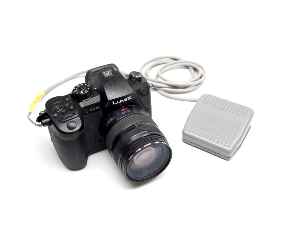
What hands-free shots will you take with your own foot pedal shutter remote?


