
Photo by Hep Svadja

Read articles from the magazine right here on Make:. Don’t have a subscription yet? Get one today.
To say Harry Potter is a cultural phenomenon is an understatement. It’s simply part of our culture, arguably as beloved as any other media franchise in history, inspiring many of us to try to capture some of the magic on our own — which is what this project is about.
After a recent trip to Universal’s Wizarding World of Harry Potter, my daughters and I decided to create a project that could use the interactive wands from the theme park, at home, to control our own props and gadgets. We called it Raspberry Potter because it was powered with a Raspberry Pi. We demonstrated the project last year at the Minneapolis/St. Paul Mini Maker Faire and this article — Ollivander’s Lamp — is the latest extension of that project.

Using wands to flush a toilet in the window of the Weasleys’ Wizard Wheezes joke shop at Universal Studios Florida. Photo by Sean O’Brien
Here’s how the Raspberry Potter works:
1. Using an infrared camera, the Raspberry Pi computer looks for small circles of reflected infrared light in its field of vision.
2. These small circles of light get tracked for movement, using OpenCV computer vision software. These patterns of movement are the gestures or “spells,” and you can make them using the reflective tip of a wand.

Figure A. Step shots by Sean O’Brien
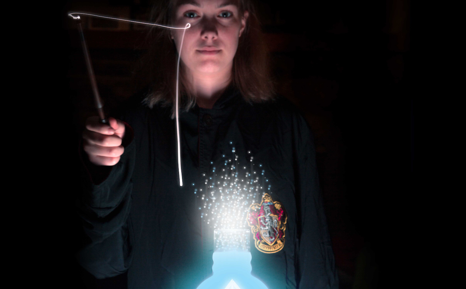
3. When the predefined patterns of movement are matched, a “spell” is cast (Figures A, B, and C) and the Raspberry Pi runs code that controls a connected device — in this case our magic lamp.
- Figure B
- Figure C
What About the Wand?

Figure D
If you don’t have an official interactive wand from the park (Figure D), don’t worry! You can easily make your own wand by gluing a sequin to the end of a stick. Any wand-like object will work fine — it only needs a reflective tip that can be used to reflect infrared light. Just make sure the sequin is shiny and flat; the faceted ones don’t work well. You can also use a “pearl sticker” such as these.

Figure E
We 3D-printed this wood-grained wand from Thingiverse and it turned out OK (Figure E). The Make: Labs used these cool-looking ones from Etsy, intended as party favors. Or check out the Raspberry Potter website for a link to my new book with detailed instructions for making your own wand.
PREPARE THE ELECTRONICS
1. Set up the Particle Photon

Figure F
Let’s start with the Particle Internet Button, which will double as our light source (Figure F) — in addition to the Particle Photon microcontroller, it offers 11 bright RGB LEDs for all sorts of possible effects.
To be honest, using this device for our purposes is complete overkill — the Internet Button offers lots of other cool functionality like Wi-Fi connectivity, directional buttons, and a 3-axis accelerometer. But it’s easy to control and fits perfectly with our hurricane lamp concept. Plus, it provides endless possibilities for extending this project in your own way. Let’s set it up, add some code, and prepare to connect it directly with the Raspberry Pi.
1a. Follow these instructions to activate the Particle Internet Button.
1b. Once activated, grab the lightsource.ino code from my Github repo. Download the code and then flash it to the Internet Button through the online console at particle.io.
1c. We’ll power the Internet Button directly through the Photon’s breakout pins: Connect a wire to the 3.3V pin and another to GND as shown in Figure G. We’ll also use the Photon’s analog GPIO pins to control the lights; connect the A0, A1, and A2 pins to the Pi after setting up the Pi.

Figure G
1d. Carefully remove the translucent plastic cover on the Internet Button. This will make the lamp just a little bit brighter. When done, it should look something like Figure H.

Figure H
2. Set up the Raspberry Pi

Figure I. Pi and camera enclosures from the original Raspberry Potter project. You’ll hide yours in Ollivander’s Lamp instead!
We’ll need to add some software packages that give the Raspberry Pi (Figure I) the ability to utilize the camera, GPIO, and some basic computer vision. We’ll assume you’re running Raspbian Jessie with Pixel as your Pi’s operating system. If you aren’t, download and install it first.
2a. Install OpenCV
Once the Pi is running and online, install OpenCV. This will probably take a few hours! OpenCV is an awesome open source computer vision project, and there’s a great installation guide for the Raspberry Pi 3 here.
2b. Install PiCamera
Now make sure the camera module is ready to go. Physically install the Pi NoIR camera to the Pi by plugging in the ribbon cable. Then run the following command on the Pi:
sudo pip install --upgrade “pic amera[array]”
sudo pip install imutils
2c. Install Pigpio
Finally, we need to install Pigpio to allow us to communicate via Python directly through the Pi’s GPIO pins. Follow the instructions under “Method 1” here. Then start up the Pigpio daemon by running:
pigpiod
2d. Install the Raspberry Potter script
Now we can download and install the Python script that runs our little project. Download the latest and greatest Raspberry Potter script from the rpotter repo on GitHub.
Attach the Pi to a monitor or display and run the script to make sure it works properly. If everything is installed correctly you should see video from your camera on the screen.
2e. Set up the daemons
Now that we know it’s running, we have to add a background process (an init daemon) so that the Raspberry Potter script will start automatically anytime we start up the device.
Go to github.com/sean-obrien/rpotter/tree/master/ollivanderslamp and download rpotter-startup. Install this file to the /etc/init.d/ directory and make it executable by running:
sudo chmod 755 /etc/init.d/rpot ter-startup
Then register the script to run at startup:
sudo update-rc.d rpotter-startu p defaults
Now unplug the Pi from the display and restart it. It should start up the script automatically and start looking for something that looks like a magic wand.
3. Connect the Pi to the Particle

Figure J
Now that our Raspberry Pi is ready to go, we’ll wire the Pi to the Photon. Figure J is a wiring diagram showing how to connect the two. You’ll also notice the commented pin references in the Photon code we downloaded earlier. Basically, connect pins A0, A1, and A2 on the Photon to pins 15, 16, and 18 respectively on the Pi. Make sure that 3.3V and GND from the Pi are connected to the Photon as well — otherwise it won’t get power!

Figure K
When we’re done, it should look something like Figure K. Figure L shows the Raspberry Pi successfully powering the Internet Button!

Figure L
4. Prepare the IR LED
Figure J also shows an infrared LED, which we’ll connect to the Pi later. Using an IR LED for illumination allows the Raspberry Potter to work in low-light conditions and even in the dark. Follow Figure J to add a resistor and power leads to the IR LED. I lazily used jumper wires (Figure M); you may want to solder yours.

Figure M
You’ll need to choose a resistance value based on your particular LED. Check out ledcalculator.net to determine what resistor you’ll need.
CREATE THE LAMP

Figure N
In the movies, Ollivander’s lamp looks a bit like an antique hurricane lamp, so that’s what I’ve based this build on. Feel free to use any kind of lamp, of course — the one I used can be found on Amazon (Figure N). We also love the Victorian hurricane lamp model by Louise Driggers but we haven’t tried to fit this project into it!
5. Modify the wick channel
It just so happens that our Particle Internet Button perfectly fits inside the lamp glass, and the base is large enough to fit our Pi — but how to wire the two together?

Figure O
If we unscrew the burner, we can remove the wick (Figure O), which gives us a hole to thread wires through.

Figure P
So far so good, but we also want to remove the wick channel (Figure P) so that the Internet Button can sit with a lower profile on the burner.

Figure Q
Remove the top of the burner, and then cut off the top of the wick channel (Figure Q) with a rotary tool, or bend it back and forth with locking pliers until it snaps off. Then reattach the collar to the burner (Figure R).

Figure R
Now we’ll be able to thread the wires from the Internet Button through the collar into the base below.
6. Frost the lamp glass

Figure S
Giving the lamp a frosted look will diffuse the Internet Button’s full-color LED light and make the lamp really glow. I just used standard Rust-Oleum frosted glass spray (Figure S) to get the effect I wanted.

Figure T
Tape off the top of the lamp glass to protect it from chips or scratches while handling it (Figure T).

Figure U
The spray takes about 5–10 minutes to dry per coat. After 5 coats, I made a stencil of the Deathly Hallows logo just so we know what universe we’re in (Figure U).

Figure V
Of course, this would be a great time to apply some creativity — maybe do a stencil of your Patronus, or a lightning bolt. Apply your stencil to the frosted glass, and coat another 5 times. Here’s what it looks like after all 10 coats (Figure V). Looking good!
7. Modify the base

Figure W
Drill 2 holes next to each other into the base of the lamp (Figure W): a larger hole for the camera lens, and a smaller hole for the IR LED. Make the holes close together, but leave enough room so that the camera board doesn’t block the hole for the LED. These holes in the picture are almost too close together.

Figure X
Now you need to open up the base of the lamp so you can insert the electronics. Cut through the bottom with a rotary tool (Figure X). We’re lucky — it’s just barely big enough for our Pi.

Figure Y
For ease of access and installation, you may want to go further and cut a bit more out of the base. Then crimp the edges using pliers, so that there aren’t any sharp edges exposed (Figure Y).
8. Mount the IR LED and Camera

Figure Z
Take the IR LED that we wired earlier and thread it through the smaller hole in the base (Figure Z). Secure the LED in place with hot glue, but first test-fit the camera board to make sure you leave enough space for it (Figure AA).

Figure AA
We need to block as much visible light from the camera as possible to allow for more accurate infrared detection. Cut a small piece of developed film or IR-pass filter plastic and cover the lens of the camera board (Figure BB).

Figure BB
Secure the camera inside the base of the lamp with its lens looking out the hole, using hot glue (Figure CC). Be careful not to burn the board or any of the wiring!

Figure CC
9. Put it all together

Figure DD
Thread the Internet Button through the collar and then attach the collar to the base (Figure DD).

Figure EE
Attach the wires from the Internet Button to the Pi as shown in the wiring diagram. Attach the LED and the camera board to the Pi as well (Figure EE). Fit all the wires and the Pi into the base and connect power to the Pi. And you’re done!
You now have your very own magic lamp.
NOW FOR SOME WITCHCRAFT AND WIZARDRY
- Figure FF
- Figure GG
- Figure HH
Inside Ollivander’s lamp, the OpenCV software is watching and waiting to track the shiny end of your magic wand. Point your wand at the lamp, then move the wand right and then up to cast the “Lumos” spell and turn the lamp on (Figure FF).
Move your wand right and then down to cast “Nox” and turn the lamp off (Figure GG).
Move your wand left and then up to cast “Incendio” for a fire effect (Figure HH).
Practice your spells in the mirror!
Making This Project Your Own
Now that you’ve done all the hard work, there’s so much more you can do to make this project your own:
» Create new light effects by modifying the lightsource.ino code. To start experimenting with colors, just replace the RGB values in the b.ledOn function with any number from 0 to 255, like this:
b.ledOn(i, 0,255,255);
This line should make all the LEDs a light-blue color. Keep experimenting to get the effects you want: strobe lights, rainbows, holiday themes, it’s all possible!
» Add spells Open up the rpotter.py script and add a gesture to IsGesture(), add a spell to Spell(), and add the corresponding pin on your Pi (copy lines 55–56 and modify for your new pin). If you’ve created something cool, send me a picture and let me know!
» Connect more props If you’re feeling ambitious, and want to try more advanced effects — say you want to switch on a fan, or trigger a servo to open a box — you can hook your lamp up to low-voltage devices through the Pi’s GPIO pins, or higher-voltage devices through a relay like a PowerSwitch Tail II.
Whether you’re a wizard or a muggle, I hope you’ve enjoyed this project — it’s been so much fun to create. As a bonus, check out the Raspberry Potter website. You can contribute your own code, and I’d love to see your ideas for new effects or improvements. You’ll also find links to other code examples and Raspberry Potter projects to try.
Cool project! I’m curious if the Raspberry Pi Zero would work for this, or if there was a reason you went with the 3?
Thanks! It may actually run on a zero, but I found that making the leap from even a 2 to a 3 made the gesture recognition much better.
Sean, would you be kind enough to take a few hours to document the process with a phone video to youtube. So many of us are probably making mistakes in the steps to reproduce your results. Thank you for your consideration.
anytime I run rpotter.py in the command line like python rpotter.py(also in virtual env) it comes with an error
Traceback (most recent call last):
File “rpotter.py”, line 22, in
import picamera
ImportError: No module named picamera
do you know how to fix it?
Oops. It looks like steps 2b and 2e have some extraneous spaces.
Even without the extra space in 2b I had trouble installing picamera. I ended up following the instructions at http://picamera.readthedocs.io/en/release-1.10/install2.html
Also, when testing the script in step 2d I had to first run the command “modprobe bcm2835-v4l2” to get the camera to be recognized by opencv.
This is great! I really want to play with this! I got everything installed, but I get an error about there being “no module named cv.” when trying to run. Been trying everything, updating libopencv-dev, working with the virtual environment and sharing the Python directory in virtual environment, everything is pointing to the right place, except obviously not :/. Be cool if you had any suggestions.
So..if I remove ‘import cv *’
I get an OpenCv error: (-215) scn ==3 || scn == 4 in function cvtColor
Which apparently means
“image should have 3 or 4 channels before applying the function cv2.cvtColor.
so check your image shape before applying the function by print im.shape. if the result is None type (most of the times, this is the problem), you image is not loaded correctly, most probably because your path is not correct.
point is that your image should have 3 dimensions, rows, columns and depth.”
I have 0 experience with OpenCv. Anyone else get this example working, or get my error?
Any luck. Just tried my had at this installed. Ended up in the same place as you. I did the CV install using the virtual environment as *strongly* recommended by the author. Not sure if this is an issue.
Nope, never got it goin
Did you have any luck fixing this issue? I’ve now come to the same point and I’m lost where to go from here
Nope, was eventually going to try to learn more about opencv and build my own version, but got busy haha.
I fixed this problem by running the script that was in the /olivanderslamp/ folder, and not the script that is up one level from that.
Note that if you’re not using the startup script, run the modprobe command that’s in the rpotter-startup script before you run the python file. If you are using the startup script, there’s no need as it runs it for you.
i was getting the same thing until i used the rpotter.py inside of the olivanders lamp folder.
Unfortunately now i have a different error.
I gathered everything, put it all together, and after an epic struggle with virtual enviroments and pigpiod and other things not working as expected … nothing. The script will now run, but I get a steady stream of “Tracking Error : ” Any clues?
Ok, the suggestion down below of running modprobe bcm2835-v4l2 was what I needed. Thanks!
Joshua, if you can find the time, would you please make a youtube video detailing each step to the finished project. And post the link here, so we can see how you got this to work.
Thank you
Joshua, can you elaborate on your pigpiod issues? That’s where I’m stuck at right now. Thanks!
I’ve been playing with it. It seems that accurate tracking might depend on getting just the right balance of filter/distance to camera/IR source intensity/having a black backdrop. Do you have some specific parameters for these things?
Hi Joshua, could you tell me how it is working within a light room? Or it requires to be in full darkness? What about having a light in front of the camera?
Total newb here. I’m trying to flash the lightsource.ino to my internet button. But I’m getting error:
rpotter.cpp:1:43: fatal error: InternetButton/InternetButton.h: No such file or directory
#include “InternetButton/InternetButton.h”
^
compilation terminated.
make[1]: *** [../build/target/user/platform-6rpotter.o] Error 1
make: *** [user] Error 2
Error: Could not compile. Please review your code.
I have earned $104,000 last year by freelancing online and I was able to do it by working part time for few hrs a day. I’m using work opportunity I stumbled upon from company that i found online and I am so happy that i earned so much money on the side. It’s very beginner-friendly and I am just so blessed that I found out about this. Here’s what I did… http://statictab.com/gpfvgtj
I got paid $104k in last twelve months by working from my home and I manage that by working part-time for 3+ hours a day. I followed a business model I found on-line and I am so happy that i earned so much extra income. It’s user friendly and I am just so happy that i discovered it. Check out what I do… http://statictab.com/6x2fxzv
Go to libraries then add the InternetButton library to your code.
If using the pearl stickers, does a certain color or diameter seem to work better?
Black and flat (or barely rounded) works the best for these.
Really neat project! Any more details on how to get this to work during the day? There’s mention of an off-the-shelf IR security spot, better filters and a brighter IR. Pointers to those would be great.
I’ve earned 104000 dollars in last twelve months by freelancing on-line and I did it by working part time for 3 or sometimes more h on daily basis. I was following an earning model I was introduced by this web-site i found on-line and I am thrilled that i made so much money. It’s really beginner friendly and I am just so happy that I found out about it. Here’s what I did… please visit my account for webpage
I was paid 104000 dollars last year by doing an on-line job and I was able to do it by working part time for 3 or sometimes more h /day. I was following work opportunity I was introduced by this company i found on-line and I am so excited that I was able to earn so much money on the side. It’s very beginner-friendly and I’m so thankful that I found out about it. This is what i do… http://twitter.com/StinnettMargar1/status/836199982713577472
I was paid 104,000 thousand dollars in 2016 by working online from my house and I did it by working in my own time for few hrs daily. I followed work model I stumbled upon from this website i found online and I am so happy that i made so much money. It’s really user-friendly and I’m so thankful that I found out about it. Here is what i do… http://easyurl.net/f2265
Looking forward to getting this all working, but I’m failing at step 2e (setting up the daemons). Upon restarting (without a monitor connected), it looks like the python process almost immediately dies. I modified the /etc/init.d script slightly to log the output to a file and what I see is that this line is output to stderr:
(Raspberry Potter:510): Gtk-WARNING **: cannot open display:
On a whim, I tried adding
export DISPLAY=:0.0
to the script and that doesn’t make a difference except that I now get
(Raspberry Potter:543): Gtk-WARNING **: cannot open display: :0.0
I was able to solve this (I think; haven’t gotten the whole thing assembled yet) by using this command in the /etc/init.d script:
echo “export DISPLAY=:0.0; python /home/pi/rpotter.py > /home/pi/rpotter.log 2> /home/pi/rpotter.err” | sudo -u pi -i &
Curious if anyone sees issues with this or has a better solution.
I got paid $104,000 last year by doing an on-line job and I did it by working in my own time for 3+ hours each day. I followed an earning model I stumbled upon online and I am so amazed that I was able to earn so much extra income. It’s really user-friendly and I’m just so happy that i learned about it. This is what i did… http://itreplaceitall.com
I got paid 104,000 bucks previous year by freelancing on-line and I was able to do it by working in my own time for 3 or sometimes more hours /daily. I’m using work model I came across from company that i found online and I am thrilled that i made so much money on the side. It’s very beginner friendly and I’m just so happy that i discovered it. This is what i do… http://s.id/272
I was having the same issue trying to run this headless. Using DISPLAY=… didn’t work for me but I seem to have found a workable solution using xvfb.
Install xvfb (apt-get install xvfb)
Change the potter startup script line “python /home/pi/rpotter.py” to “xvfb-run python /home/pi/rpotter.py”
I have yet to install the project in a lamp and am still waiting for my IR source but this passed my initial headless tests.
Did the IR array work out for you?
Tracking Error:
infinite line above when I try to run rpotter.py and no display just black window.
Help
I was paid 104000 bucks last year by doing an online job and I manage to accomplish that by working part-time for several h daily. I was following an earning opportunity I found on-line and I am so happy that i earned such great money. It’s so user friendly and I’m just so grateful that i found this. Here is what i did… http://gee.su/XbrAK
which rpotter.py did you use? the one in the main directory or the one in the olivanders lamp folder? The one in olivanders lamp is much newer. i had that error before but switched files. of course now i have a different error.
If you’re like me, you might not have noticed that there are TWO rpotter.py files in the repo. The one you want is in the ollivanderslamp folder (note the differences in version and last modified date–you want the more recent one, of course). It took me longer than I care to admit to figure this out.
The problem with the older version of the file (on the root level of the repo) is that it seems to rely on an older version of OpenCV (2.4.10, maybe). There is no cv.so in OpenCV 3, so there’s no importing to be done.
Also, camera initialization failed for me, and I completely missed the comment below about modprobe, so I decided to make it hard on myself and rewrote the initialization to use PiCamera() instead of cv2.VideoCapture. In doing this, I also had to change up how the frames were parsed (see the test_video.py tutorial at http://www.pyimagesearch.com/2015/03/30/accessing-the-raspberry-pi-camera-with-opencv-and-python ). Thankfully, it required only a few minor modifications.
Edit: ran modprobe as mentioned below and reran the old script, and everything works beautifully.
Hey Joshua, can you describe how you installed pigpiod? When i run the rpotter.py I get an error stating no module named pigpio. Thanks!
I saw where it looks like you got past this bit. Since I was using a dedicated Pi, I ended up not using a virtual environment, which solved a lot of weirdness that I was seeing the first time around. Not sure if this was exactly what fixed the pigpiod issues, but there was definitely some conflict (likely user error).
Yeah I had to add the pigpiod files to the virtual environment and it started up. Now I’m having trouble getting the wand to get noticed. I have one from Universal so I know it’s not the tip. I think it might be the IR led or maybe I don’t have the right filter over the camera. What IR led and camera filter did you use?
I did manage to get wand reflection working, but I also did some testing by stringing a few wires together and using the LED itself as the “wand”. One thing to try if you haven’t already is to shine a phone camera at the LED to check brightness.
I used the suggested IR LED – Adafruit #387.
There was a tiny piece of film that shipped with the camera itself that I ended up using–I don’t know if it was intended to be used as a filter, but it actually worked well enough.
The first resistor I tried made the LED entirely too dim (I forget the resistance–500ish, probably). It was quite bright with no resistor, though I’m not sure how much I was risking killing the LED entirely.
If you run the script without the film, OpenCV will just detect all sorts of points and treat point 0 as the “wand”. I was able to turn on the lamp with my hand, for example, though not reliably.
Also, even when I did get everything up and running, as others have mentioned, it struggles to keep up. You’ll need to move the wand pretty slowly. I saw where changing the default framerate might help, but I didn’t know about this when I was testing.
I have a similar experience. The tracking is too slow and jittery. OpenCV is finding too many points unless room is all dark. Filter is a good help. But the tracking (left-up, for example) matches too easily unless you are slow and precise.
I’m looking for improving the OpenCV tracking somehow (learning gestures? limiting the area that is tracked?)
Anytime I run rpotter.py in the command line like python rpotter.py(also in virtual env) it comes with an error Traceback (most recent call last):
File “rpotter.py”, line 22, in
import picamera
ImportError: No module named picamera
Try pip install –upgrade –user “picamera[array]”
Note that you’ll need to be in your virtual environment when you do this, if you set up an environment with virtualenv.
Would someone who has got this working be kind enough to make a youtube video of the steps. Lumos!
I agree. I need help with this project. Thanks!
Agreed
So I managed to get a great error when trying step 3 (connecting the photon button to the pi).
I’ve followed all the instructions, if I run the rpotter script (after the modprobe command) I can see the camera image popup when the board is connected to a screen. I was able to flash the program to the button, had some jumpers, good to go.
Connected it all up, started pigpiod, then ran the rpotter script manually and – the pi rebooted. Then it rebooted again, and again, and again. Had to unplug it. Now, it doesn’t happen when I only have 3.3v connection and ground running to the button, but it does when I have the jumpers on – and even if I unplug the jumpers during the reboot mania, still keeps rebooting.
The button is lighting up the whole time and had the nice slowly blinking light on, so it seems to be working fine.
The video is super slow. Is anyone else having the same slow video issue. I’m running this over ssh and using the regular rpotter script, not the start up script. Its so slow, recognition of the wand takes a while and is difficult. Then you need to move the wand super slow so the camera can see it. Otherwise it blurs and the camera loses the tracking.
Anyone else having this issue? Anyone know of any other Harry Potter wand programs?
Did you ever resolve this? I’m having a similar issue. Not sure if the IR filter isn’t block enough or what…
I did get this to work much better. I do not recall exactly what I did, but looking through my links, I was searching OpenCV, Video, Slow, Raspberry Pi. I’ll paste my searches below.
The first link here seems to have some possible solutions:
https://www.raspberrypi.org/forums/viewtopic.php?f=43&t=80128
Other info
https://www.raspberrypi.org/forums/viewtopic.php?f=43&t=80128
https://raspberrypi.stackexchange.com/questions/15379/options-for-slow-camera-via-opencv
https://duckduckgo.com/?q=open+cv+raspberry+pi+slow&ia=web
Hope that helps
My cv2 appears to be setup for python 2 and my picamera is set up for python 3 in the virtual environment. How can I reconcile this? Would like to have picamera work with python 2 in virtual environment because I assume it would take longer to adjust the cv code.
Did you figure this out? I’m of no help but wondering it is my issue as well. I’m a complete rookie but diving in head first.
How do you know they are setup for the different Pythons? (Want to check if that my issue.)
Small bug: It isnt sudo pip install –upgrade “pic amera[array]” (2b), but sudo pip install — upgrade “picamera[array]”
Anyone fine some cheap IR filters for this?
Did anyone come across the ImportError: No module named pigpio? I have everything loaded and have tried it in and out of the cv environment. Any help would be greatly appreciated. Thanks!
Ok got it working. Looks like you need to copy the pigpio files into the /home/pi/.virtualenvs/cv/lib/python2.7/site-packages folder and then run the rpotter.py script. Now onto the next step!
8GB is really not big enough for the SD Card. Recommend at least 16GB.
This is a super cool project that I am working on for my wife. Running into some of the same issues but different
Running on Pi3
Installed OpenCV 3.1 (reading might need OpenCV 2)
Tried inside and outside CV
Tried the modprobe command
I’m not using the special internet button. Was going to just turn LEDs on and off. Is that an issue?
I’m a rookie at Raspberry Pi
Currently getting this error:
Traceback (most recent call last):
File “rpotter.py”, line 33, in
warnings.filterwarnings(“ignore”, category=np.VisibleDeprecationWarning)
AttributeError: ‘module’ object has no attribute ‘VisibleDeprecationWarning’
Sean mentioned a raspberrypotter.com but it doesn’t go anywhere for me. Any ideas on that?
curious if anyone has gotten this to work the way it was described. I think I’ve got it kinda working, but can’t see how I can mount it into something better looking. The only way it runs is if I have it connected to a monitor and mouse, then run a series of commands to get it into the “virtual environment” as demanded by the OpenCV installation. This does not seem to work with the startup script as supplied above, and I can’t get it to boot up into the rpotter.py script.
1) Could my problem be the use of a virtual environment? How do I install without it?
2) How do I get a startup script to execute a series of steps? The things I needed to do:
source ~/.profile
workon cv
sudo pigpiod
sudo modprobe bcm2835-4l2
python rpotter.py
I tried inserting this into the rpotter-startup script but nothing happened.
Did you ever get it figured out? If not, I got it all working so I might be able to help.
I got it working by the tracking is too sensitive. How did you get the hardware setup? I have a single IR LED. Thinking of wiring a few.
I ended up scrapping the built in LED and making my own “IR wand” with a push button to control the LED. Mine is the one on the top https://uploads.disquscdn.com/images/f5ca7f4a1d7073e49b150c79b4f40dd3f2a2b2c62b9bf833a59c847efad2e3b5.jpg
I don’t know if people are still having issues with getting the program to run as illustrated in the Tutorial but if so I figured out a few things to resolve a few issues.
Firstly, getting the rpotter.py program to run without opening a command prompt and accessing the virtualenv:
I created a new script (calling it “testing.py”) and used subprocesses to log into cv:
#! /bin/sh
import subprocess
python_bin = “/home/pi/.virtualenvs/cv/bin/python2”
script_file = “/home/pi/rpotter.py”
subprocess.Popen([python_bin, script_file])
Secondly, I could never get the rpotter-startup file to properly work. I made it executable, added it to init.d like suggested by the author. So I instead made a simple script with the following code:
#!/bin/sh
#launcher.sh
#navigate to home directory, then to this directory, then execute python script, then back home
### BEGIN INIT INFO
# Provides: launcher.sh
# Required-Start: $remote_fs $syslog
# Required-Stop: $remote_fs $syslog
# Default-Start: 2 3 4 5
# Default-Stop: 0 1 6
# Short-Description: Simple script to start Raspberry Potter and pigpio at boot
# Description: A simple script based on a script from http://www.stuffaboutcode.com which will start / stop a program a boot / shutdown.
### END INIT INFO
export DISPLAY=:0.0
cd /
cd /home/pi
sudo python testing.py
cd /
Finally, from the command prompt type the following to access your .bashrc file:
sudo nano -e ~/.bashrc
Then, scroll all the way to the bottom and add the following line:
ssh /etc/init.d/launcher.sh
Simply replace “/etc/init.d/launcher.sh” with the path to your version of the previous script.
Afterwards, save by hitting Ctrl O and then [return] and exit with Ctrl X.
Upon reboot you should find the rpotter.py script runs automatically. I hope this helps. If anyone has any other questions I’m happy to help if I can.
Trying to do as project with my son. I am stuck on the LED and resistor stage. I purchased the ADA fruit IR LED #387. Can someone please suggest an appropriate resistor? Thank you.
Did you ever find out what resistor to use?
Not yet
This is a bit tricky – if you haven’t figured it out yet, here are my thoughts:
The tutorial recommends using ledcalculator.net
Here is the info you’ll need:
Power Supply: 3.3V (if powering from the Pi 3.3V line)
LED voltage drop (V): 1.6V
LED Current Rating: 100ma
Based off those parameters, you’ll want an 18 Ohm resistor.
Per on the datasheet, I think the LED should still operate when its running as low as 20ma, meaning the highest resistor you could use is 90 Ohms (which should still work, it just won’t be as bright)
Datasheet URL: https://cdn-shop.adafruit.com/datasheets/IR333_A_datasheet.pdf
Thank you so much!!! A great help!