In 1764, scotsman James Watt grew thoughtful as he tinkered with the machinery associated with his job as a steam engine technician. The main problem with those early steam engines, called Newcomen engines, was that they were terribly inefficient. They were a step up from draft horses, but Newcomen engines went through coal like a starving man on a Christmas ham.

This inefficiency, thought Watt, was simply unacceptable, and he believed he could do better. When Watt put his mind to a task, he was a nearly unstoppable force. Besides his preternatural drive and determination, he possessed, as English historian Samuel Smiles said, “a keen eye for details, with which he combined a comprehensive grasp of intellect.” In fairly short order, Watt made radical improvements to the early steam engines, boosting their efficiency and utility. Those improved Watt engines changed the world, leading to the Industrial Revolution in England, America, and beyond.

But Watt wasn’t finished yet. One of the many engine-related inventions for which Watt is credited is the flyball or centrifugal governor. In the early days of the Industrial Revolution, most engine operators in mills and mines needed to keep their machines turning at a constant rate of speed, irrespective of the load placed on them. Generally the speed of an engine increases when the load decreases, so, for example, if a pump removing water from a mine shaft needed to operate at 70rpm, then the operator had to manually open or close the steam valve whenever the amount of water in the mine shaft changed.

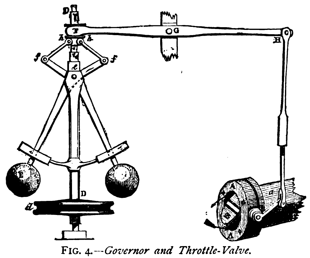
In 1788, Watt began to think about a way to make this happen automatically. His solution was the flyball governor. The flyball governor is based on the idea of a feedback control loop. It works like this: Weighted balls are linked via hinged arms to the shaft of a steam engine. As the engine turns faster, the hinged flyballs fly apart. But, as the balls separate, a linkage causes the throttle on the steam engine to close.

Less steam means the engine slows down and the flyballs come back together. But, when they get too close to one another, the linkage causes the throttle to reopen and the engine speeds up again, and thus an endless loop of engine speed adjustment ensues. If designed well, the flyball governor maintains a fairly constant engine speed, no matter what the load.

While Watt didn’t originate the concept of the centrifugal governor (Christiaan Huygens invented one for clocks, see “Poetry in Motion,” page 40) or the feedback loop, his is one of the first important examples of the idea in use in large machines.

In this edition of Remaking History, we make a James Watt-style flyball governor. Since few of us have steam valves and boilers readily available for a project, we’ll use the electricity from a couple 9-volt batteries in place of the boiler, and a pair of aluminum brushes instead of a steam valve. This simplified, on-off rendition of Watt’s world-changing wonder is cheap to build, fairly easy to make, and great fun to show off to friends and family.

Build an Electrica Flyball Governor

There are four main components of this flyball governor project: the shaft, the base, the flyball linkage, and the control brushes.

Project Steps

1.

Use the sandpaper to reduce the diameter of the dowel until the aluminum shaft collar slides easily along its full length. Then, drill a 5/16″ hole through the dowel 2½” from the top.

2.

Place a small amount of glue on the bottom end of the dowel. Place the aluminum mounting hub on the dowel and center it as perfectly as you can. Let the glue dry. Once dry, hammer the brads into the holes on the mounting hub to permanently secure it to the dowel.

3.

Drill three 5/32″ holes, 120° apart, in the wall of the pipe flange. Cut bolt threads into each hole using a #10-24 tap. Screw the #10 machine screws into the holes. You can find instructions for tapping threads in metal at makezine.com/2011/03/22/skill-set-the-basics-of-tap-and-die.

4.

Using the Forstner bit, cut a 2″diameter flat-bottomed “blind” hole, 3/8″ deep, in the center of the top surface of the wooden support as shown below. Then, using the center mark made by the bit, cut a 11/16″ hole through the center of the blind hole.

5.

Follow the instructions in the above image to build a wooden shaft support using the 2×4 boards and the 1×10 board.

6.

Place the modified pipe flange in the middle of the 1×10 board, centered directly under the 11/16″ hole. Fasten the flange with the #10×¾” wood screws. The Flyballs and Linkage 7. Drill 7/64″ holes in the center of the 9½” and 10″ aluminum strips.

8.

Bend the 9½” and 10″ aluminum strips into U shapes as shown below.

9.

Using a 13/64″ bit, drill and then tap a ¼–20 threaded hole, ¾” deep, in each wooden ball.

10.

Use the vise and pliers to bend the 7¾” aluminum strips into the shape depicted below.

Then, add a 90° twist as shown below. These are the brushes.

11.

Drill two 7/64″ holes 180° apart on opposite sides of the shaft collar for twine attachments. Cut 6-32 threads in the holes. Screw the 6-32×¾” bolts into the threaded holes.

12.

Insert the motor into the flange opening.

13.

Place the bearing in the 2″ blind hole.

14.

Insert the shaft, hub down, through the center of the bearing. Connect the hub to the motor shaft using the setscrew and Allen wrench that came with it. Check and adjust to make sure the shaft spins true and easily. Then fasten the motor in the flange by tightening the #10 bolts.

15.

Slide the aluminum shaft collar onto the wooden shaft.

16.

Attach the aluminum motor brushes to the wooden support frame as shown above using the #8×¾” wood screws. Gently bend the aluminum as needed so that it just clears the shaft, but supports the shaft collar as shown.

17.

Assemble the flyball linkage (the 3″ hex bolt, nuts, and plastic washers) as depicted above and attach to the wooden shaft as shown.

18.

Connect a 10″ length of mason twine between the attachments on the shaft collar and the outboard shaft nuts as shown above.

19.

Use the alligator clips to complete an electrical circuit between the motor, batteries, and brushes as shown below. (If the motor contacts are under the flange, splice in a wire to the contacts so you can connect the alligator clip.)

How Your Flyball Governor Works

When you complete the electrical connection, the motor shaft will rotate. As it rotates, centrifugal force causes the balls to fly outward, causing the mason twine to lift the aluminum shaft collar off the brushes, disconnecting the circuit and causing the motor to slow down. But, the slower rotation means the flyballs will move inward again and the shaft collar will lower once again upon the aluminum brushes, remaking the electrical connection. When this happens, the motor speeds back up.

This is an example of a feedback control loop: The unending cycle of making and breaking the electrical contacts ensures the motor rotation speed stays within a narrow band, providing more or less constant RPM, irrespective of the load placed upon it. James Watt would be proud!

Operation Notes

  • Wear safety glasses whenever the shaft is in motion.
  • For safety, do not let the shaft turn at speeds greater than 90rpm. You can adjust the rotational speed by making the mason twine lengths or aluminum brushes longer or shorter.
  • Secure all threaded connections with thread-locker adhesive to prevent nuts and balls coming loose.
  • The make-and-break style circuit results in tiny sparks as the machine rotates. These sparks will eventually leave a nonconductive residue on the aluminum brushes and collar, which must be sanded off periodically for best performance.