When you’re getting started in robotics, building a self-balancing bot is a rite of passage.
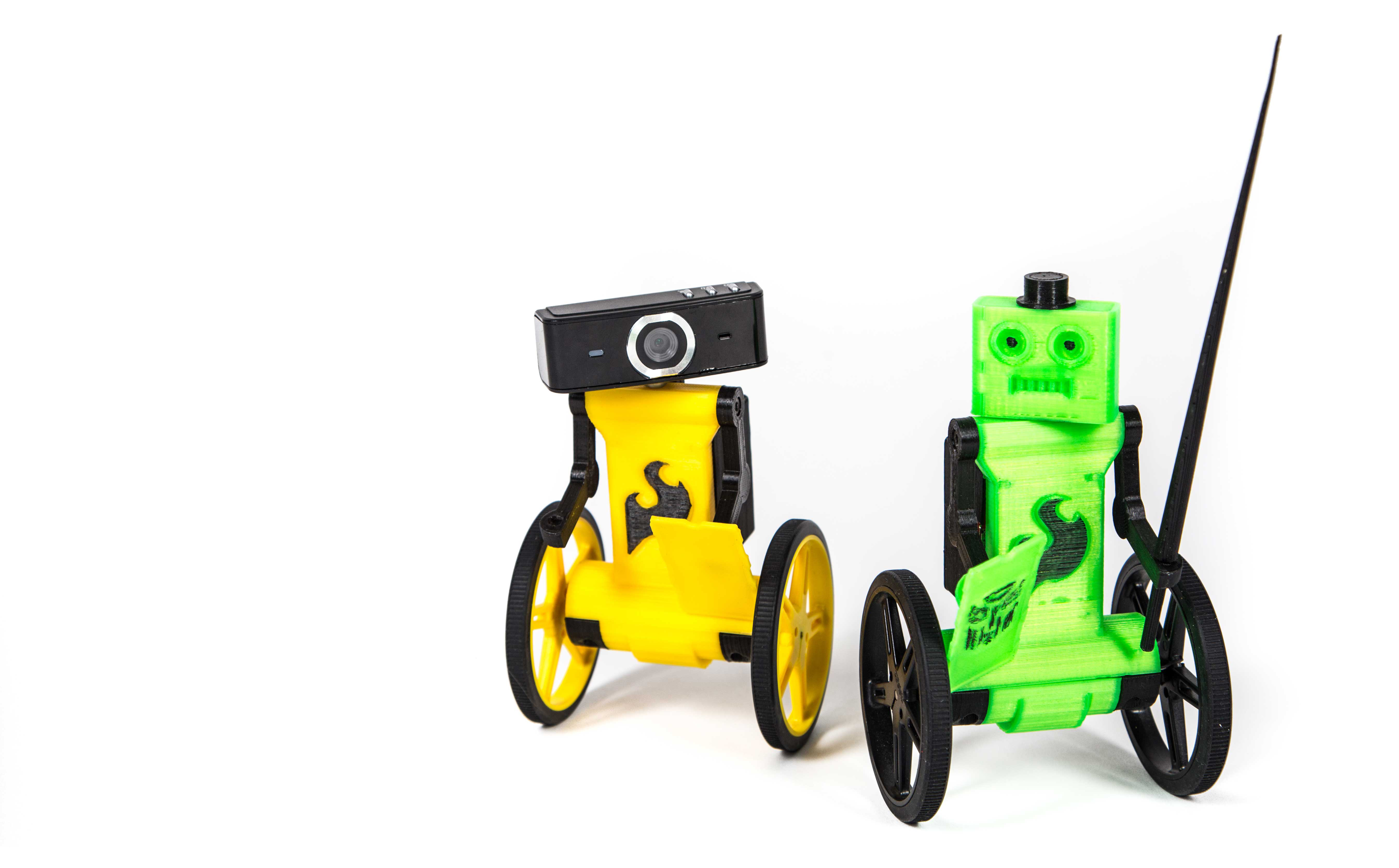
Mine is called EddiePlus. He’s rechargeable, Wi-Fi-enabled, and remote controlled, and he’s an open source project, so anyone can build him in a weekend or two. He can even be navigated completely out of sight, for 1 hour of drive time, via an FPV (first-person view) camera.
I built my first Eddie just for fun and as an excuse to put my Intel Edison Compute Module to good use. As a customer eagerly awaiting the Edison release, I was excited to have a project planned before my order arrived. The Edison’s low power draw and tiny footprint make it a great fit for small, battery-powered projects that need a lot of processing power. I was also excited to try SparkFun’s Edison Blocks — modular boards that stack onto the Edison to provide functions like motor control and power management.
Now Eddie is back and he’s excited to show off his improvements. EddiePlus has a cleaner look and vastly improved performance. He’s got all the original features, plus new motor encoders, dynamic balance, dual PID control on each wheel, and faster motors and bigger wheels for more speed. His design has been updated to add interchangeable heads and a “backpack” enclosure to keep the electronics safe.
Eddie has Windows, iOS, and Python apps you can use to command him via Wi-Fi. You can get his source code on GitHub, and I’m maintaining an assembly guide on Google Docs.
Let’s build him!
Project Steps
1. Install the encoders
Notice the arrow that I drew on the motor? It’s pointing toward the side of the gearbox that has no gears in the first half (Figure A). Orient the encoder’s 6 connectors toward this side of the motor as shown, then follow the manufacturer’s instructions on the Pololu product page to solder them in place and install their magnetic discs.
Note: Be sure to install the encoders nice and flush with the bottom of the motor.
2. Mount the motors
Now install the motors on the EddiePlus body using the printed motor mounts and M2×14mm hex screws or self-tapping screws. Orient the motors with their encoders as shown in Figure B, and press-fit them into the indentations inside the motor mount. Once installed, the motors should be almost perfectly flush with the edge of the body and motor mount.
Note: These photos were taken when I was using M2 screws to hold the motor mounts. After stripping out too many Eddie bodies, I changed the motor mount design to accommodate more robust self-tapping screws. As a bonus, the screw heads are completely hidden in the new motor mounts.
3. Install the Battery Block
First attach the M2×5mm standoffs to the back of the EddiePlus body, followed by a set of M2×3mm standoffs (Figure C) to give the Battery Block enough clearance (Figure D).
Also make sure that the battery fits within the standoffs; you’ll probably need to reposition it.
Note: Every Battery Block I’ve received has had the battery pre-installed, requiring me to unstick the battery so it can be repositioned to fit within the 4 standoffs. Take care not to bend the PCB if you have to re-stick your battery.
4. Install the GPIO Block
This is where the fun begins! You’ll need a short section (about 100mm) of ribbon cable 6 wires wide. Prepare one end of the cable by stripping the shielding on all 6 wires and tinning the ends (applying solder) to keep them from fraying apart.
Start by soldering the leftmost wire of the ribbon cable (as viewed in Figure E) to power on the GPIO Block, then solder the rightmost wire to GND on the opposite side.
Using a razor or hobby knife, carefully separate the middle 4 wires to reach the GPIO breakouts, then solder them, from left to right, to GPIO pads 44, 45, 46, and 183.
Note: I’m using 3.3V levels but if you’re so inclined you could use VSYS (~4VDC).
Using a Sharpie I marked the edge wire for GND and added dashes to the 2 wires used on the left encoder (Figure F). I also blackened the seven GPIOs that are not available due to the Dual H-Bridge Block.
5. Wire GPIO Block to encoders
Yes, the soldering fun continues. First, stack the GPIO Block on the Battery Block with another set of 3mm standoffs.
Solder the 3.3V wire to one encoder’s VCC pad, and the GND wire to the other encoder’s GND pad (Figure G). Then, using 2 short wires, bridge both power and ground to the opposite encoder (Figure H).
Finally, solder the encoders’ signal wires to pads A and B on both the left and right encoders (Figure I). Here’s the connection table:
Encoder to GPIO Connection | ||
GPIO 44 | Right Encoder | B connection |
GPIO 45 | Right Encoder | A connection |
GPIO 46 | Left Encoder | B connection |
GPIO 183 | Left Encoder | A connection |
Once you’ve made it this far, go ahead and give yourself a pat on the back. Be sure none of the wires are touching the encoder magnets, and you should be in good shape.
Now, because the GPIO Block uses the TXB0108 chip for level shifting, you need to add a 5K pull-up resistor to each of the
4 encoder signal connections (Figures J and K). Without these resistors the auto-direction sensing in the TXB0108
will not allow the encoder signals to reach the Edison.
Note: These are the smallest 5K resistors I had on hand. They work but are a little bulky.
To prevent motors from running during boot, a pull-down resistor is also used on GPIO 49. This prevents the TXB0108’s default high-impedance state from bringing the dual H-bridge out of standby mode while the system is booting. I tested these:
Tested pull-down resistors on GPIO 49 |
||
4.7K | NO | Stays high at boot |
3.9K | YES | Works |
1.8K | YES | Works |
6. Wire and install the Dual H-Bridge Block
Start with about 120mm of ribbon cable that’s 4 wires wide. Solder these to pads A1, A2, B1, and B2 on the Dual H-Bridge Block.
Next add a solder bridge to connect the VSYS->VIN pads (Figure L). This will allow the battery power to drive the motors.
Install the PCB using 3mm standoffs and wrap the wires around to the bottom side (Figure M). Be sure not to pinch or put a kink anywhere in the ribbon cable, as this will diminish the motor’s drive power.
The wires on the right side go to the right motor (Figure N). The rightmost wire is B1 on the H-bridge and connects to M1 on the encoder. The adjacent wire connects to M2 on the right encoder.
The remaining wires on the left side go to the left motor (Figure O). The leftmost wire is A1 on the H-bridge and connects to M1 on the encoder. The adjacent wire connects to M2 on the left encoder.
7. Install the Base Block
Before you install the Base Block, I recommend putting about 3 layers of electrical tape over the USB connectors so no conductive metal is exposed (Figure P). If you don’t, you’ll see that they’re dangerously close to contacting the H-bridge output.
8. Install the IMU and the Edison
The 9DOF IMU is the last block in the stack and you’ll secure your Edison on top of it (Figure Q).
On this build, I used the M1.5 screws and M1.5×3mm spacers from an Edison Mini Breakout Kit. I’ve also had success with M2×3mm screws and standoffs, but watch out for the tiny traces next to the holes. You don’t want to cause any trouble.
9. Install motor cover and wheels
The motor cover should press-fit with a minimal amount of pressure and stay in place without screws (Figure R). There’s enough clearance for the ribbon cable to wrap around the underside of the GPIO Block and not be pinched by the cover.
When installing the wheels I recommend using your index finger and thumb to apply pressure to the motor mount and body while pushing the wheel in place. The motors do lock in place when installed properly but I’d hate for something to go wrong when pushing the wheel onto the output shaft.
10. Finishing touches
Slip the “backpack” cover over the electronics stack, then install the arms using the M3×14mm screws (Figure S). You can adjust their position so that Eddie can carry a variety of loads.
Finally, install the head of your choice using the M3×5mm screw (Figures T and U) — or mount your USB webcam instead (Figure V).
Congratulations! You’ve made it. You’re ready to install the EddieBalance code and bring your robot to life.
Setting Up Your Edison for Eddie the Balance Bot
» Update the OS
Download the latest Yocto image. Then follow the Intel Flash Tool instructions for your operating system.
» Log in via serial
Now you need to establish a serial connection to Eddie. To do this, connect a micro-USB cable to your computer and to Eddie’s right rear USB port (the one labeled “Console”). Turn him on and place him lying on his backpack.
WINDOWS: Use Putty to establish a serial connection with the USB Port under the Serial tab in the Putty config screen, and make sure the Speed value is set to 115200 baud for Eddie’s communication. If you’re unfamiliar with Putty, just Google “set up putty serial”.
OS X: Plug the USB cable into your computer, open Terminal and type:
ls /dev/ | grep usb
Copy the tty.usbserial-[SOMEVALUE] to a text file. Using this value, type:
screen /dev/tty.usbserial
[SOMEVALUE] 115200
to connect to Eddie.
Once the Edison is booted, press Enter in the terminal and it will prompt you to log in. The login is root; there’s no password yet.
» Connect Eddie to Wi-Fi
Now that you’re logged into the Edison, run:
configure_edison --setup
Follow the prompts to configure your hostname and password, and to connect Eddie to your Wi-Fi network.
Note: If you ever need to connect Eddie to a different Wi-Fi network, log in and run:
configure_edison --wifi
to set up a new connection. Reboot, and Eddie will be discoverable by his apps if you’ve configured the startup service in the extras directory.
» Install dependencies
Yocto Linux uses opkg as its package manager. AlexT’s unofficial opkg repository is highly recommended for adding packages to your Edison. It includes many useful packages such as git and libmraa. To configure the repository, first open the file /etc/opkg/base-feeds.conf and add the following lines:
src/gz all http://repo.opkg.net/edison/repo/all
src/gz edison http://repo.opkg.net/edison/repo/edison
src/gz core2-32 http://repo.opkg.net/edison/repo/core2-32
Then, still logged into the Edison, run:
opkg update
opkg install git
» Install the EddieBalance software
Recommended from /home/root, now run:
git clone https://github.com/
r3n33/EddieBalance.git
To ensure everything is ready to go, run:
/home/root/EddieBalance/src/./
build
No output means everything compiled OK and you’re ready to test your Eddie bot.
To test your Eddie robot, now run:
/home/root/EddieBalance/src/./
EddieBalance
If you’d like to make the EddieBalance software run at boot, follow the instructions found in the readme file at /home/root/EddieBalance/extras/README.md.
The EddieBalance software listens for data on 2 ports; one for gaining control and the other for sending commands. And Eddie returns data to the last IP received on the response port.
Follow the instructions on the Github page to “bind” Eddie to your computer for remote control. The bind process was a necessary evil to allow multiple Eddie robots on the same Wi-Fi network. Bluetooth control is next on my list of features.
Let’s Roll!
Driving Your Eddie Balance Bot
EddiePlus loves to dance, can adapt to varying carry loads (Figure W), and doesn’t mind slopes (Figure X). I made some lances and shields for my Eddies (Figure Y) and then pitted them against each other in a jousting tournament (Figure Z).
You can drive your Eddie via remote control over Wi-Fi, using one of 3 apps:
» I’ve shared a Windows application for controlling Eddie, that lets you view and manage the PID data (Figure AA) and even drive around using WSAD keys. Download it from my server here.
Place Eddie on the floor upright, power him up, and gently hold him until he self-balances, being careful of his backward movement. Connect your computer to the same Wi-Fi network you connected Eddie to, and run the control software. At the bottom of the panel, click the Find button and choose your Eddie’s profile from the list. Near the top right of the panel, press Stream On. You should start receiving telemetry data and you can now control Eddie’s motion with the WASD keys.
» I’ve also developed an iPhone app (Figures BB and CC) for controlling Eddie; it’s a beta but you can install it using Impactor following these instructions.
» There’s also a Python-based controller written by Eddie builder William Radigan, hosted on GitHub.
Adding an FPV Camera
I have done full FPV remote control of Eddie by streaming the video to a web browser, using edi-cam software. I’ve also successfully streamed video to my iPhone app, but there hasn’t been a lot of development time for that and it’s currently disabled in the app (maybe you can help develop it!).
The main problem I had was the video had a “bobbing” effect due to the camera being fixed on the pitch axis. Still, I was able to drive Eddie around my (former) office while he was out of sight. Definitely fun! Then again if a robot is involved I’m almost automatically having fun.
The USB camera I used was a $5 eBay item. Find the smallest one you can, then it’s a simple matter of soldering a short micro-USB cable to the camera’s PCB, to plug into the OTG port in the Base Block.
Going Further
Sure, there are easier and cheaper ways to build a balancing bot, but they’d come at a cost — like size, features, or weight. For the feature set Eddie has, I don’t think you can do much better on the price unless you’re a very savvy shopper. You can sometimes find SparkFun coupons, or open-box Edisons for half price at Micro Center. If I were to rework this project to cut costs, I’d eliminate the SparkFun Blocks and design my own PCB with the required components.
It’s easy to make this project your own by editing the 3D-printed parts to give Eddie different looks. For starters, you can model alternate heads (Figure DD) and allow room for a hex standoff in the base to make them interchangeable.
I’m also working on Bluetooth control, but haven’t finished yet; I’ve shared my updates and findings at this git branch.
I hope you enjoy your Eddie, and I hope you’ll expand and improve upon my design. If you do — or you just need help building your Eddie — please send me a message on Twitter @EddieBalance.