This article appeared in Make: Vol. 90. Subscribe for the latest maker projects and articles!

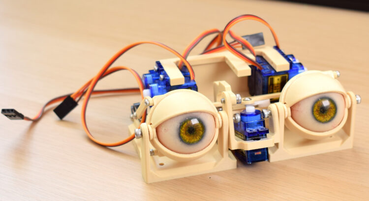
Animatronics, once relegated to the realms of theme parks and big-budget movie sets, are experiencing a renaissance in our DIY culture. Perhaps it’s childhood nostalgia, certain horror-themed video game franchises, or the desire to explore the intersection of technology and artistry. Whatever the reason, there’s excitement surrounding the creation of animatronic marvels. And amidst this wave of enthusiasm, there’s never been a better time to embark on your own animatronic journey! In this project you’ll build a realistic eye mechanism you can control with a joystick — and integrate into any project you like!

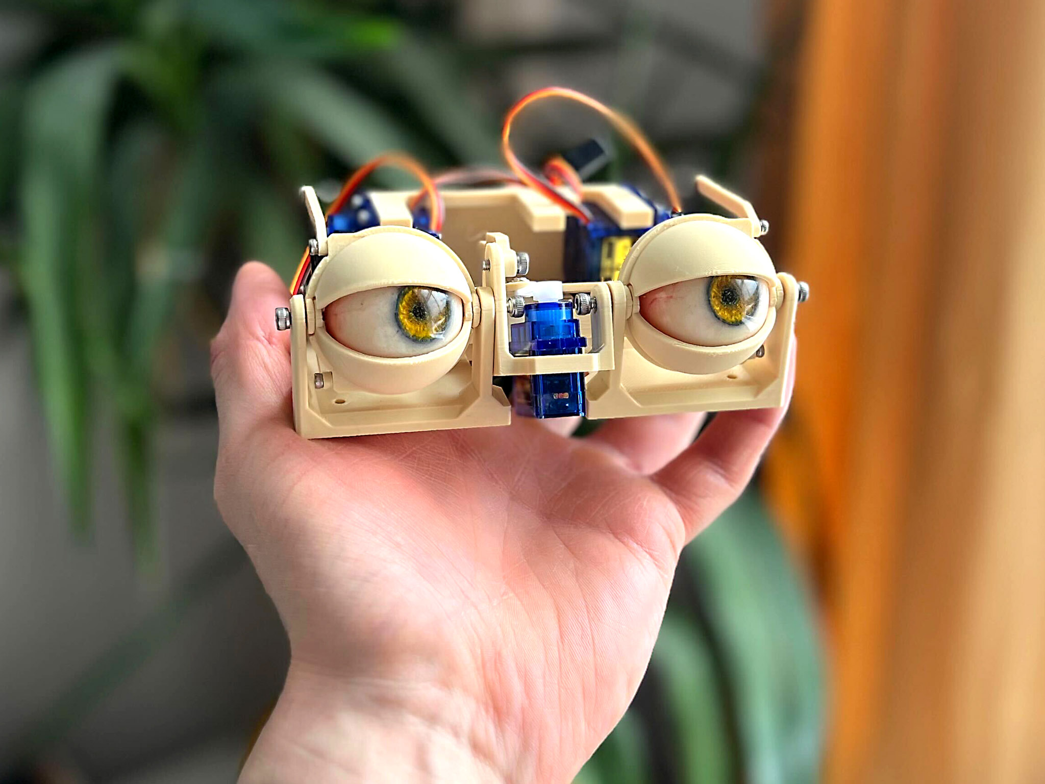
To start with, my code will allow you to look left and right, up and down. As the gaze moves up or down, I’ve programmed the eyelids to follow them subtly which adds a surprising amount of realism. Using a button, you can also trigger a rapid blink. Since we’re using a programmable Arduino you could also write your own code to move the eyes autonomously or even integrate them into a larger animatronics project!

Project Steps

1. Printing

With a healthy printer, printing should be no issue without supports. There are some thin sections and snap-fits so you might benefit from printing with a stronger material like ASA or PETG, but I used PLA and had no trouble at all. 0.2mm layer height is a good guideline.

Download the files for printing. Note that I have a few different options for the eyes — a blank, round version, a version with an iris and pupil cutout, and a highly realistic version you can build as a whole separate project! I designed them all to use a common interface, so they attach with a snap-fit to my “eye adaptors” as they’re called in the download pack. But you can use anything else so long as it’s 32mm diameter or less and can fit the eye adaptor!

You may want to do some sanding on the inside of the eyelids since the 3D printer would’ve been printing an overhang in this area and the gap between the lids and eyeballs is quite small. The parts are designed to print such that some holes are undersized enough to be directly screwed into, whereas others are oversized enough so the screw will pass through and allow for rotation. If your printer’s not the most accurate, you can use a drill to adjust any hole sizes which are too tight for smooth movement.

2. Assembly

Connect the two bases with 10mm or 12mm M3 bolts. This pivot point is for the y-axis of the eye motion and the eyelids.

Place the servo in position and screw it in with some 4mm or 6mm M2 screws. This serves as the actuator for the x-axis motion.

Photography by Will Cogley

Attach the y-axis arm to the sub-base with a 4/5/6mm M3 screw, and attach a servo horn on the third hole from the center using a 4mm or 6mm M2 screw, as shown. Check to make sure the orientation of everything is right.

Start building the x-axis assemblyby screwing the forks into the eye-adaptors with 4/5/6mm M3 bolts. The fork holes should be oversized so the screws bite into the adaptor. One goes in on a funny angle but you should be able to get it in.

Attach the three-point connector to the top of the forks; the M3 screw will bite into the undersized hole in the fork component. Also attach a servo arm on the final hole to the center of the three-point connector using a 5mm M3 bolt (the hole on the servo arm will likely need to be drilled to 2.5mm–2.8mm to accept the screw). I’d recommend manipulating the assembly regularly as you build it up, to make sure it all moves OK without friction.

Attach the eye center-link to the eye adaptors with an 8mm M3 screw, making sure the flat surface of the center-link is facing up and the sloping section is facing down. You can also plug in the eyes at this stage.

Screw all this to the center of the sub-base with two 12mm M3 bolts.

Load up the servo block with five TowerPro SG90 servos, in the correct orientation shown. Attach it to the base with four M3×10mm bolts.

Work out which eyelid is which using the photo below. Connect the relevant connector with a 4mm or 6mm M2 screw, and attach a servo arm to the other end, using the last hole in the servo horn — you may need to drill this to 1.5mm–1.8mm.

Attach the eyelids to the base, but don’t worry about connecting any servo horns yet.

Photography by Will Cogley

3. Wiring, Code, and Finishing Up

Upload the code to the Arduino, and wire everything up. Check the Adafruit guide if you need help setting up the servo driver board, but all you should need to do is download the Adafruit Servo Driver Arduino library.

All servos should now be powered and in their neutral position, so use this opportunity to link up all the servo arms to the servos, with the eyes facing straight forward in a neutral position. You can just plug them in while powered up, then disconnect the power to screw them in properly. The y-axis servo arm is in an awkward position to accept a screw, but I found that it held fine without a screw anyway. If yours doesn’t, it may be helpful to remove one of the eyelid servos to screw it in. I’d recommend testing the motion with your joystick at this stage to make sure there are no issues.

For the eyelids, it’s best if you attach the arms of the servo while they’re in the blinking position so you can line up all four of them in the center. Do this by holding down the blink switch or creating a short circuit over it. Once all the servo arms are in position, pop a screw in to keep them secure.

4. Operation and Integration

Your model should be complete! Now you can put eyes in your pumpkin, T-800, or animatronic pizza bear. Using the joystick, the eyes will follow the direction you point in, and the eyelids will move very slightly to match the position of the eyes. Pressing the button will make the eyelids snap to the center, so by pressing it quickly you’ll get a fast and realistic blink. The potentiometer is there to allow you to adjust how open/closed the eyelids are at rest, so you can turn it down to get a sleepy look or turn it up to look more alert.

If you want to build on this project and add extra animatronic parts, there are still plenty of pins on the Arduino and driver board to allow you to add to it. And if you already have a larger animatronic project you’d like to integrate these eyes into, you can simply swap the inputs from the joystick, potentiometer, and button for signal cables from your larger project’s controller. You can control the direction with an analog signal through pins A0/A1, and the openness from A2, and send a high/low digital signal for blink.

Conclusion

Eyeball These Builds From the Community!

Here’s a look at some of my favorite animatronic eyeball builds from makers around the world!


This article appeared in Make: Vol. 90. Find updates at NM Robots or Will’s YouTube channel. Subscribe to get the latest maker projects and articles!