Jon G. Aguado is a Spanish aerospace engineer living and working in Austria. He is an active enthusiast of self-made gadgets that can make his life easier. He’d love to receive feedback on any of his available boards @jgaguado
This article appeared in Make: Vol. 90. Subscribe for more maker projects and articles!
Until recently, I relied on the Xiaomi Mi Flora to monitor my indoor plants. While it provided useful plant care info, it had some interface limitations, requiring their specific app for configuration. One day, I noticed some missing data and suspected the battery had died. However, upon searching for the sensor, it was nowhere to be found.
I organized a search party that morning and, after gathering clues and speaking to witnesses, discovered that a neighborhood raven had taken the gadget for its collection of stolen items.
AI-generated sketch of the suspected thief at the crime scene.
Dall-E 3 (Bing Image Creator)
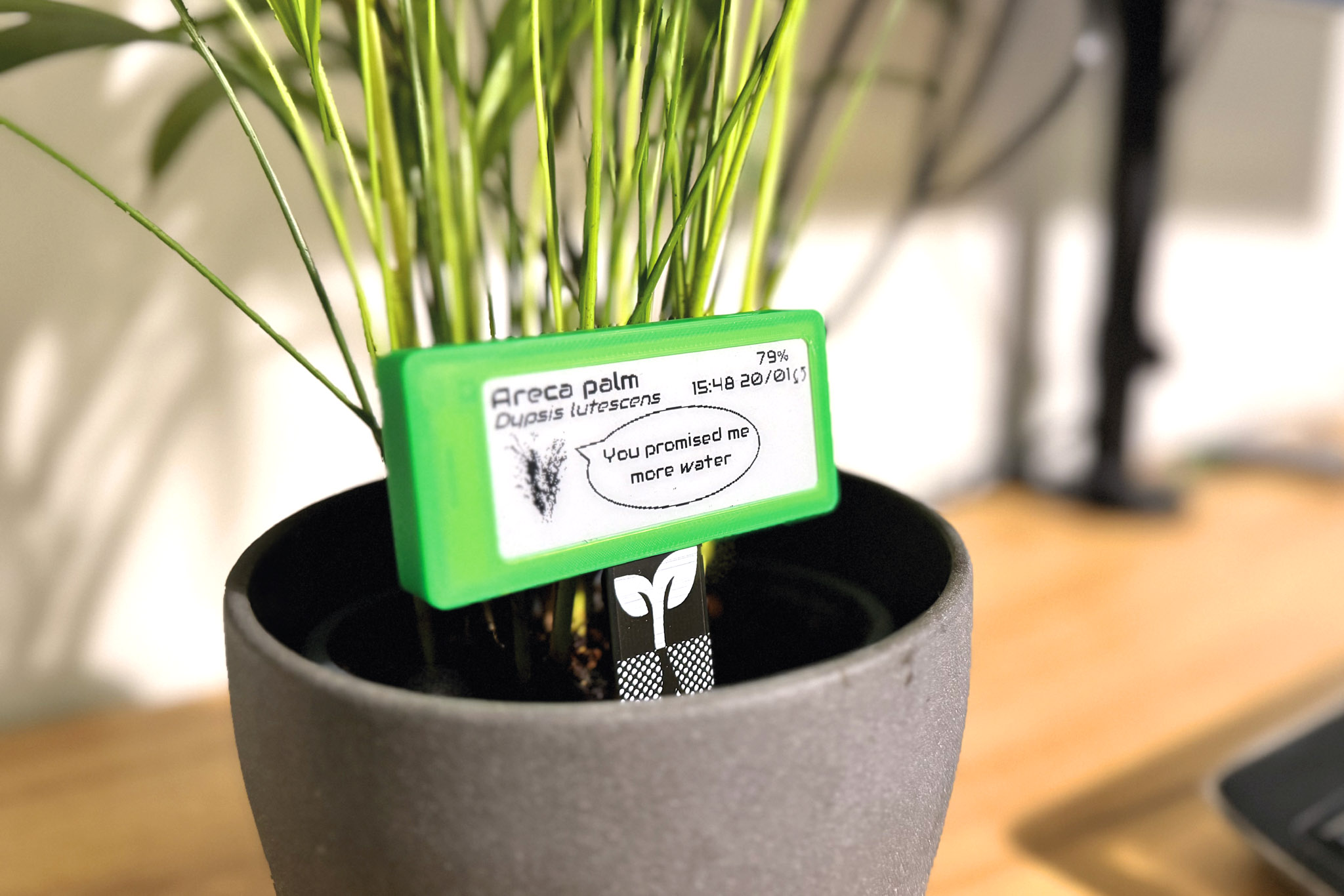
This incident inspired my next project, the Smart Plant — an open source plant monitor with Wi-Fi connectivity that also displays data directly on the board. Here I’ll show how you can solder my through-hole prototype. If you like it you can go full SMT with my latest version or buy one on Elecrow to play with.
Project Steps
1. Component Selection
For my prototypes, prioritizing low power consumption and my fondness for e-paper displays, I opted for LilyGo’s T5 2.13″ e-ink development board. This board features an ESP32 with Wi-Fi and Bluetooth capabilities, a 2.13″ e-paper display, and essential circuitry for battery charging and protection, among other functionality.
Next, I chose the sensors for measuring my plants’ vital parameters. With the intention of simplifying the assembly process by mounting everything on a protoboard and minimizing complexity, I opted for digital sensors. This decision meant I only needed to solder a maximum of four pins (I²C bus + power), with the convenience of receiving measurements in physical units.
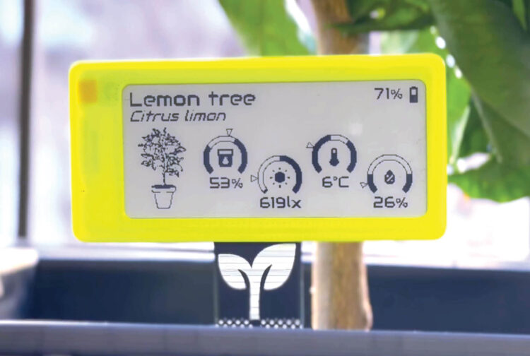
SMT version of Smart Plant showing off the e-ink screen
My primary criterion was to select sensors that had already been tested and proven compatible with the ESPHome framework. For the light sensor, I selected the Maxim MAX44009, conveniently available on a compact purple module called GY-49. And for the temperature sensor, I repurposed an old GY-BM module containing a Bosch BMP280, which not only measures temperature with an accuracy of ±1.0°C but also provides barometric pressure readings.
Lastly, I chose a standard capacitive soil moisture sensor board with a simple 3-pin interface (GND, VCC, and AOUT). Although the output is analog, I planned to calibrate it as needed.
In the initial design revision, one sacrifice I had to make was omitting the measurement of soil fertility, which relies on soil electrical conductivity (EC) and necessitates adding corrosive-resistant pads to the PCB.
NOTE: Some capacitive soil moisture sensors are poorly designed and may even replace important components with inferior parts to be cheaper. This might result in shorter lifespans and/or wrong measurements.
2. Assembly
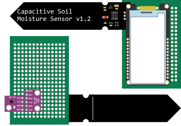
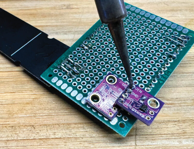
With all the materials prepared for assembly, you’ll begin by positioning them on the prototype board as depicted.
The LilyGo module is not mounted directly on the protoboard; instead you’ll use the female headers shown.
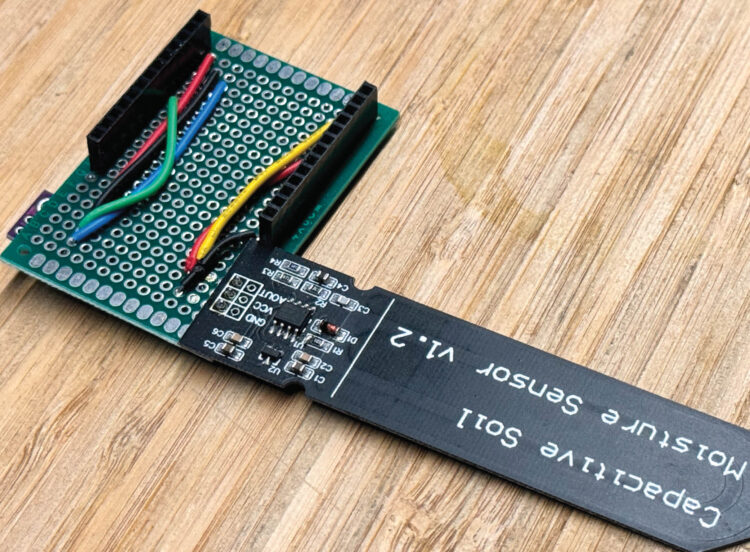
Photography by Jon García Aguado
In this position, the components will be almost aligned, so you’ll have fewer, and shorter, wires to solder.
3. Soldering
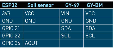
With all the components in position, proceed with soldering the connections between the pins and wires according to the Pinout Table.
Pinout Table
Since the GY-49 and GY-BM modules have their 4 pins aligned, I decided to stack them and solder them together.
After you solder all the components and connections, I highly recommend that you check your connections with a multimeter. This way you make sure there are no short circuits that can damage the LilyGo T5 ESP32 module, and you can verify the continuity of your connections to avoid hardware errors.
Caution: Always solder in safe environments, paying special attention to ensure that smoke does not drift into your eyes or lungs, and be mindful of the hot parts you’ve recently soldered.
4. Programming
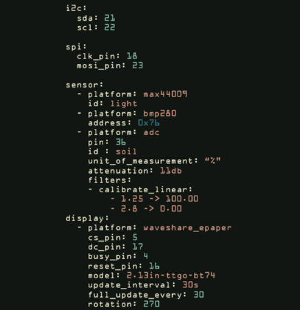
With all the hardware assembled, you can proceed with programming the ESP32. While Arduino is a common choice, for this project I’ve opted for ESPHome, a firmware that’s powerful and easy to configure for home automation projects. One of its standout features is its seamless integration and direct communication with Home Assistant. Since all the selected sensor modules are directly supported as Sensor Components on ESPHome, the configuration YAML file looks similar to this screenshot.
After you flash the LilyGo with the ESPHome firmware, calibrating the soil moisture sensor is necessary. This can be achieved by inserting the probe into soils representing 0% and 100% moisture levels, then noting the corresponding readings. This data allows for later application of a linear calibration.
Conclusion
Going further with the hardware
After multiple iterations and extensive testing of sensors, I’ve reached Smart Plant version V2R1, which embodies numerous lessons learned. Key enhancements include digital sensors compatible with deep-sleep mode, battery charging and monitoring capabilities, support for a solar panel, and a layout conducive to a two-part 3D printed case. You can get the 3D files, PCB files, and schematics at smart-plant.readthedocs.io.
Daily usage
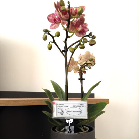
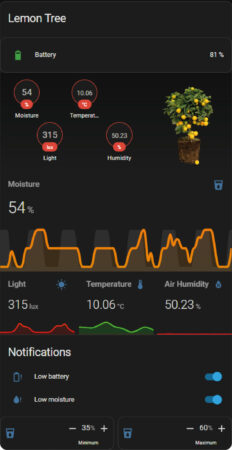
One of the most valuable features of the Smart Plant is its ability to display data not only numerically but also with gauge indicators referencing recommended ranges. To obtain these indicators I automated the background generation (with the gauges, ranges, plant names and sketches) through a Python script and ChatGPT.
Furthermore, ESPHome can be customized to display messages based on various scenarios, such as time or parameters exceeding recommended values.
The seamless integration of ESPHome-flashed devices with Home Assistant simplifies the creation of dashboard cards like the one depicted here. This enables me to remotely monitor the plant’s status via a web browser or smartphone.
During the summer, some plants outside on the balcony benefit from an automated irrigation system. This system waters them based on each plant’s actual needs and the weather forecast, thereby reducing water waste and ensuring optimal plant care.
After all, perhaps that raven was just a silent guardian, a watchful protector. A dark knight that simply wanted to help me improve my plants’ well-being.
If you found this project interesting and want to dive deeper into the documentation, visit: smart-plant.readthedocs.io
This article appeared in Make: Vol. 90. Subscribe for more maker projects and articles!
Jon G. Aguado is a Spanish aerospace engineer living and working in Austria. He is an active enthusiast of self-made gadgets that can make his life easier. He’d love to receive feedback on any of his available boards @jgaguado