Due to popular demand, I’ve decided to take my MakerGear Mosaic assembly guide one step further, past the physical assembly of the robot, and cover the process of getting through the first print. What started as a series of seven guides is now a series of eight:
- the frame
- the Y-axis
- the X-axis
- the Z-axis
- the extruder
- the build platform
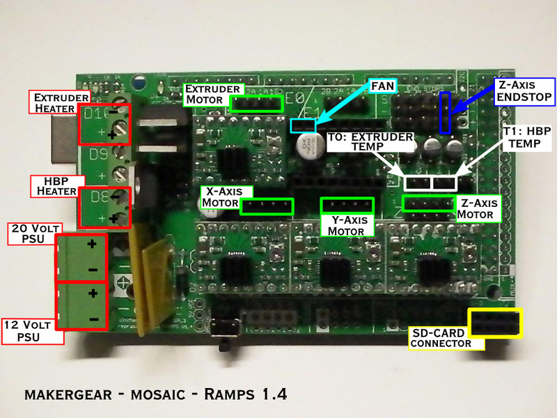
- the electronics
- the first print
Once you have the robot itself built, the number of possible ways to set up and run the printer start to multiply rapidly. Your options and preferences will vary based on the computer you’re using, the operating system on that computer, and the CAD, CAM, and printer control programs you choose. Unfortunately, I can only report what’s worked for me. If your experience is different, and it may well be, please feel free to comment below and tell us about it.
I chose to dedicate an old laptop to my Mosaic. Specifically, it is a Toshiba Satellite A25-S207 running Windows XP SP 3. I don’t ask it to do much else while it’s running the printer, except occasionally capture time-lapse images of an ongoing print using an attached webcam. There’s a PCMCIA WiFi card I can pop in when I need internet, but I don’t usually leave it connected to the web.
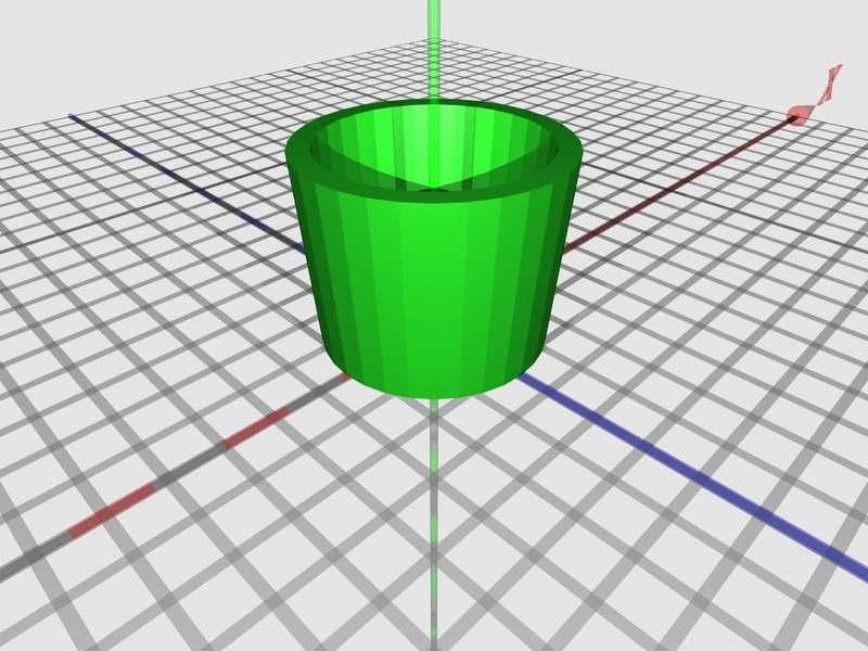
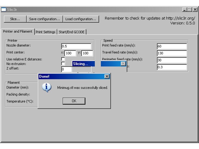
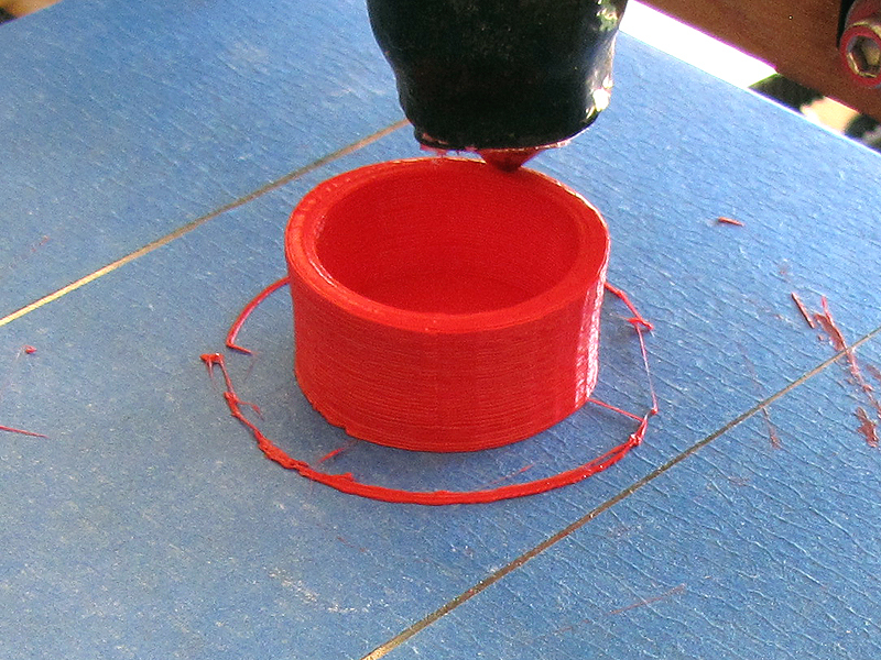
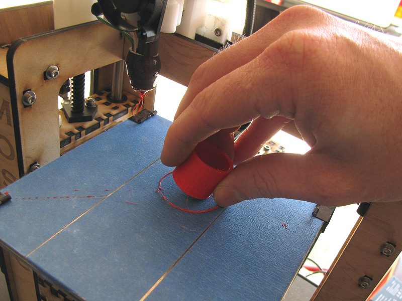
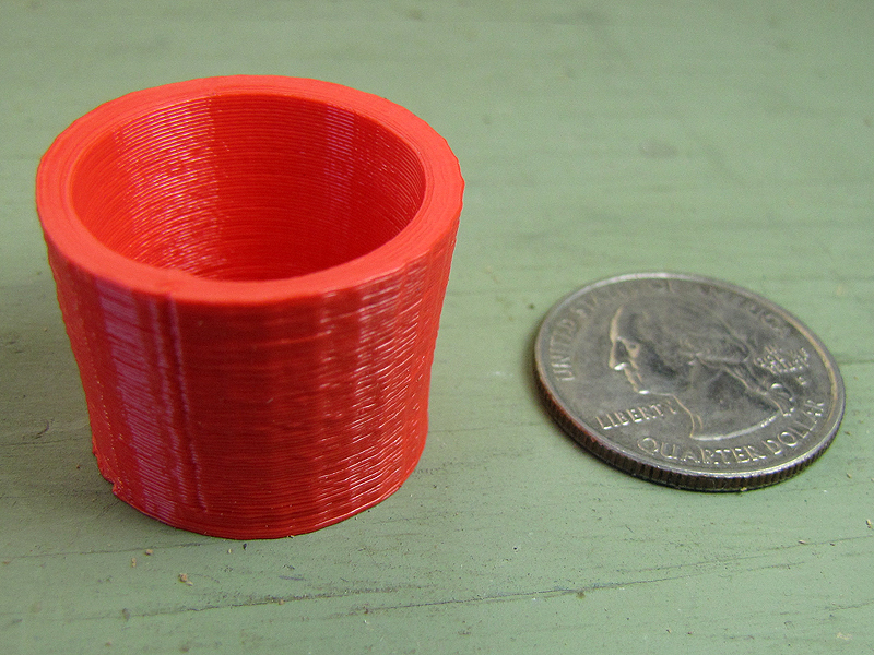
This tutorial does not cover 3D modelling, and assumes you will be using a downloaded .STL file. Traditionally, the first print off of a RepRap is supposed to be a shot glass, and the traditional file is minimug.stl. The original file is available on the RepRap wiki, but for whatever reasons it is rotated at an unprintable angle, which is inconvenient for beginners.
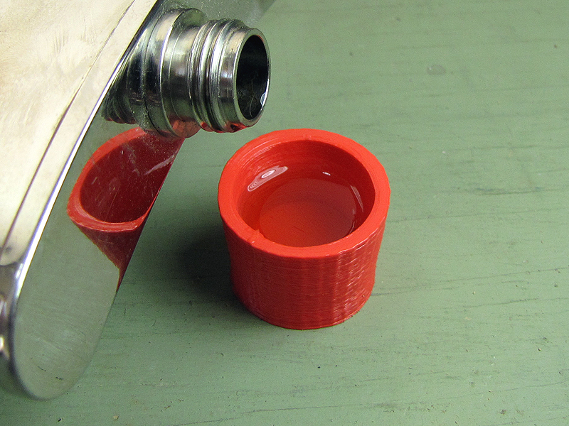
What you put in it, of course, is up to you, but I’ve found Glenfiddich Solera Reserve to be an excellent, if pricey, test fluid. Solely on the basis of its viscosity, you understand.
Though there are more exotic possibilities, generally you will be printing in either ABS (Acrylonitrile Butadiene Styrene) or PLA (Polylactic Acid). Of the two, I find PLA preferable in pretty much every way. It prints cleaner, in my experience, does not emit noxious odors, and melts at a lower temperature. You’ll want to experiment with ABS yourself, of course, and see if you agree with my assessment. But I think you should start out with PLA. Your Mosaic kit probably included a couple of short coils of PLA in different colors.