


Building a makerspace from scratch has been both a challenge and a huge opportunity. The first and most important step was securing a property with all the right ingredients for a makerspace. After that, we engaged Cho Ben Holback and Associates (CBHA), a respected Baltimore firm with a deep portfolio of university studio buildings, as our architect. Diane Cho, partner, and Ethan Marchant, project architect, were assigned to the project, and have done terrific work on a complex job.
CBHA began the process by sending us a detailed programming survey. According to the American Institute of Architects (AIA), the program is the “. . . systematic evaluation of the interrelated values, goals, facts, and needs of a client’s organization, facility users, and the surrounding community.” A programming survey is a useful exercise for any makerspace planning process – it will really help clarify your needs, your wants, and your blue-sky ideas based on budget and available space.
CBHA divided their questions into several sections. First, they asked about general design goals like aesthetic direction, sustainability, and what workshops needed to be included. Then, they asked specific questions about each room: communication needs, acoustic isolation, power requirements, access control, adjacency, capacity, ventilation, and humidity control. In order to answer down to this level of detail, we dipped back into our research about other spaces to see how they had solved similar problems. It also forced us to take a deeper dive into our needs, researching equipment lists and figuring out our basic business model.
Once we had programmed the building, it was time for the architects to get to work. Their first step was to field-measure the building and generate an “as-built” drawing of the base conditions. Once they had something to work from, we moved through the standard professional architectural design process, following a set of steps that gradually iterate towards a final plan.

1. Test fit (4 weeks): the architect generated a series of “bubble diagrams”: hand-drawn sketches, roughly to scale, that tested several different potential layouts for adjacency and fit. At this point, there was no indication of circulation space or site design.
2. Schematic design (8 weeks): once we were sure everything was going to fit, the architect started iterating scaled floor plans in the computer using Revit. This step begins to take into account things like hallways, fire exits, and some of the other code-mandated aspects of a building. We had a few rounds of iteration at this stage before we settled on the final plan.

3. Design development (8 weeks): for the DD set, the architect began to think in three dimensions, pulling the design up from the plan and looking at elevations, sections, and site considerations. A whole new set of details is layered into the design, including handicap access, window placement, signage, and stairs.
4. Construction set (12 weeks): the architect’s near-final set of plans, where all of the tiny issues are resolved. A series of outside consultants – mechanical, civil, and electrical engineers, a landscape architect, and a signage designer – were brought on to design all of the sub-systems in the building.
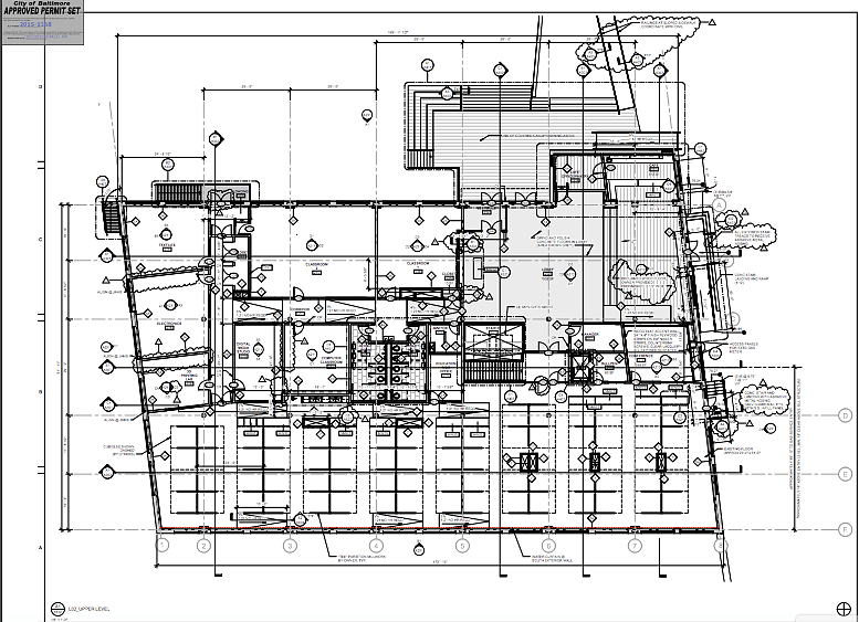
5. Permit set (8 weeks): the set of drawings that the architect submitted to the city in order to pull a building permit. The permit set for our project was about 200 pages, and faced review by the fire marshal, the water department, and the building authority. It is accompanied by a schedule; a very thick binder that specifies every door, lockset, window, roofing product, paint color, and so on. The schedule is keyed to the blueprints with a series of callouts so that contractors know exactly what to install and where to install it. Our review took several months; depending on the municipality, the process can vary widely.
The whole process took roughly 10 months. That timeline was driven by scale and complication; if we had made our mind up faster about certain aspects, or had a simpler program, it could’ve progressed much more quickly. Along the way, we had our general contractor price the project twice. While imprecise (based on incomplete drawings), these periodic estimates helped us check whether our costs were in line with our projections and fundraising goals.
You can apply this same process if you are designing your space yourself: evaluate needs, measure your space, work out a rough floor plan, then move to the computer to refine your layout. There is lots of decent free software out there that can help you, including SketchUp, FreeCAD, and Autodesk’s free consumer-grade packages. For field measuring, check out Magic Plan, which allows you to use a phone or tablet to map your space with remarkable accuracy by locating corners with the camera. Pair 3D, a new app (made in Maryland!), allows you to generate a 3D map of your space by scanning with a tablet, then drag-and-drop furniture into it from their model library. For site planning, Google Earth is great for a broad overview; for measured drawings, you’ll have to check in with your city’s planning department to get a plat map.
As you iterate forward, a host of detailed questions will arise – how high should a countertop be? What is the acceptable slope for a handicapped ramp? What are the fire-safety standards for a wood shop? For these types of questions, you’ll need to tap into architecture’s holy trinity: the International Building Code (IBC), Occupational Safety and Health Administration (OSHA) rules, and Architectural Graphic Standards. Most municipal building codes are based on the IBC, which should give you a good framework for meeting permit requirements on technical issues. OSHA standards will govern decisions about venting, dust collection, and other hazard prevention in the workshops. Architectural Graphic Standards is a manual that explains every possible standard dimension of every possible building component, piece of furniture, and landscape feature. As you go, you’ll have to keep a list of prospective equipment with power requirements in order to design the electrical schematics.
Even if your budget is limited, it pays to assemble a team of experts. If you can’t meet market rate for the services of engineers and architects, see if you can barter with future memberships, ask if they will donate their services pro-bono, or engage a non-profit like the Neighborhood Design Center to help out. If you already have a membership group organized online, recruit professionals willing to help out from that pool. It can be really, really difficult to get a through the building permit and zoning processes without some professional assistance. Taking shortcuts on the design side will lead to compromised space at best, and a downright dangerous one at worst.
For our next Made in Baltimore post, we’ll examine Open Work’s equipment list in greater detail and explain how we arrived at our mix of facilities.
Construction Update
Since the last post, we have:
1. Installed four skylights.
2. Began HVAC installation upstairs.
3. Installed most of the windows.
4. Insulated walls and roughed-in drywall.


ADVERTISEMENT


