


Software is a key piece of digital fabrication. Numerous programs exist that let you design digital models, and others convert those models into commands for your specific machine, allowing it to produce physical builds. Autodesk’s Fusion 360 has become one of the go-to software options for makers that offers both of these elements. It is light and intuitive while integrating computer-assisted design (CAD) modules such as free-form modeling, rendering, assembly, and physical simulation. And you can even use it to aid in fabrication processes like CNC milling with its computer-aided manufacturing (CAM) module.
If you want to learn Fusion 360 and are coming from a 3D-modeling environment such as Inventor, Pro-Engineer, Catia, or Solid Edge, the switch shouldn’t be too painful. The biggest difference is using A360, Autodesk’s cloud platform which houses and shares your designs. I like this feature, and even wonder now how I lived without it, especially when I work with a team.

Let’s review the CAM module, which can export toolpaths in a variety of formats, to prepare complex designs for CNC milling.
First create a Setup, where you select the type of milling you wish to do (Fusion 360 also supports turning), specify the stock’s dimensions, and place the bit’s starting point.
Next, apply a different type of successive milling operation (pocket clearing, parallel, 2D contour, etc.) to clear the excess material. For each of these operations, the proper tool (bull nose mill, ball end mill, chamfer mill, etc. — learn more here) needs to be selected. If your tool isn’t on the list, you can create a profile in the tool library to add it. From there, you’ll need to make some choices, from the height and tolerance of each pass, to the use of tabs — which keep your model in place until you manually saw it out, rather than it being carved loose and compromising its position while underway.
Satisfied with the simulation of the generated toolpaths? Then just send it to post-processing in a format your CNC machine will recognize.

Things You Should Know
Overall, Fusion 360 gives a great “design to manufacturing” experience. Here is a simple exercise showing how I turned a vector drawing into a wooden bas-relief.
While you can easily import a large selection of 3D files directly into the Fusion 360 workspace, it is currently very difficult to use embedded mesh volumes, such as STL or OBJ with the CAM module. While tools to convert mesh into solids do exist in the software, they won’t work with large or complex files. Don’t despair! Mesh modeling is on the 2016 improvement schedule, but until then, it might be tricky to mill your favorite Thingiverse designs.
Turn a Vector Drawing into a Wooden Bas-relief

1. Fusion 360 can insert an SVG drawing as a sketch from a selected plane. Here, I used a vector drawing of our beloved Makey.

2. Before importing your vector file, create a sketch and draw a line measuring the length you would like your drawing to be. This will facilitate more accurate scaling. All closed areas will appear in clear orange, which means they can be used for 3D functions.

3. The modeling tools are fairly straightforward: You’ll use Extrude, Revolve, Fillet, and Mirror to create this 3D Makey.

4. The first 3D toolpath generated is an Adaptive Clearing with a ⅛” flat end mill. The robot measures 6½”.

5. In this case, the second toolpath is a 2D Contour following the part’s bottom outline, using the same mill as the previous action. To keep the model locked in place until the end of the milling, you can enable the Tabs and choose their shape, thickness, and position. I set mine to triangular, 3mm wide, and with a thickness of 0.75mm.

6. The last toolpath applied to finish this model is a Parallel pass using a ⅛” ball end mill. The closer the passes, the better the result, but also the longer it will take. An SBP file was exported directly from Fusion 360’s Post
Processing tool.

7. For this milling, I used a ShopBot Desktop with a board of Valcromat MDF dyed red. Here’s the result after the Adaptive clearing.

8. After the 2D Contour and the Parallel pass, following the X axis.
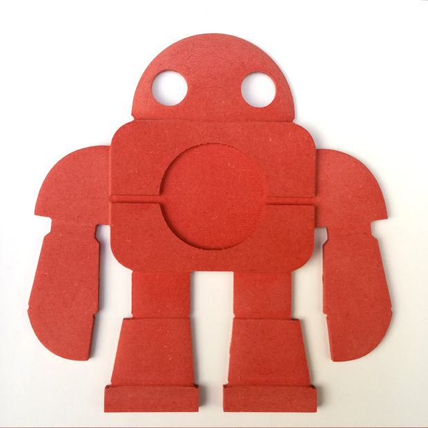
9. The Makey was easily removed from the board, using the tip of a flat screwdriver to cut the Tabs.

10. A little bit of sandpaper, clear varnish to bring out the color, and a laser-cut “M” is all you need to finish this awesome MDF Makey!

ADVERTISEMENT


